Figure 3.11 – Rockwell Automation 1394 SERCOS Interface Multi-Axis Motion Control System Installation Manual User Manual
Page 75
Publication 1394-IN002B-EN-P — February 2004
Connecting Your 1394 SERCOS Interface System
3-21
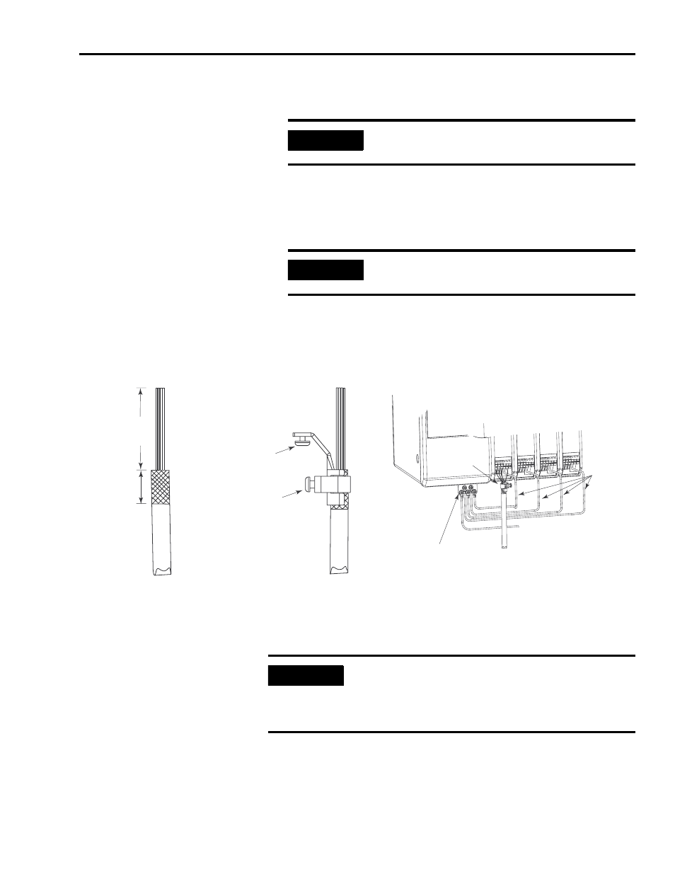
5. Remove another 22 mm (0.875 in.) of insulation to expose the
braided shield underneath for clamp attachment.
6. Position the cable shield clamp over the exposed braided shield
(ensure clamp screw is behind clamp and not braided shield).
7. Tighten the clamp screw.
8. Thread the bracket screw into the bottom of the axis module and
tighten.
Figure 3.11
Motor Power Cable Clamp Preparation
1
Dimensions given are approximate and will vary depending on the specific installation. Keep wires as short as
possible while maintaining adequate stress relief.
2
Remove plastic (captive) washer, if present.
IMPORTANT
When cutting into the insulation use care not to
cut into the braided shield underneath.
IMPORTANT
Do not overtighten the clamp screw or damage
to the braided shield may result.
Cable wires
Braided
shield
exposed
51 mm
(2.0 in.)
1
22 mm
(.875 in.)
1
Motor
cable
Bracket
screw
2
Clamp
screw
Clamp
shield
clamp
Cable Preparation
Cable Attachment
Wiring to Axis Module
System module
single point bond bar
Motor
power
cable
Axis
cable clamp
1394 Front View
To bonded
cabinet ground bus
or power distribution ground
PE1
connections
IMPORTANT
If your 1394x-AM75 axis module requires 10 mm
2
(8
AWG) cable, replace the clamp that shipped with
your axis module with catalog number 1394C-8AWG-
GCLAMP.