1394 system power dissipation specifications, System modules axis modules – Rockwell Automation 1394 SERCOS Interface Multi-Axis Motion Control System Installation Manual User Manual
Page 111
Publication 1394-IN002B-EN-P — February 2004
Specifications and Dimensions
A-7
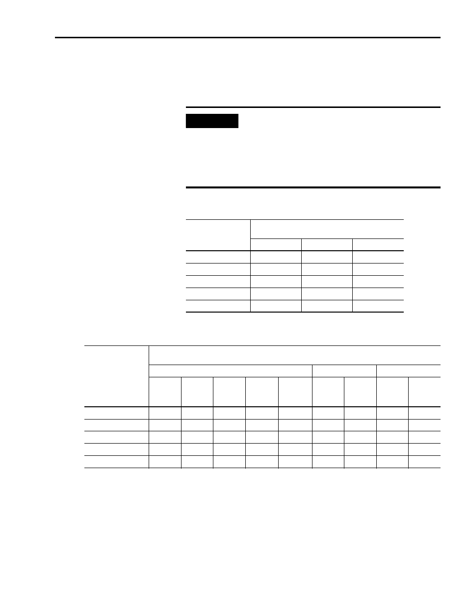
1394 System Power Dissipation Specifications
The following section contains the power dissipation characteristics of
the 1394 system modules, axis modules, and internal shunt resistors.
System Modules
Axis Modules
1
The AM50/75 are designed to mount with the rear heat sink extended outside the customer-supplied enclosure. If
the modules are mounted entirely inside the customer supplied enclosure, the full power dissipation is inside the
cabinet (the sum of the inside/outside columns).
2
The AM50/75-IH are designed to mount entirely inside the customer-supplied enclosure.
IMPORTANT
Use the power dissipation figures shown below to
calculate cumulative system heat dissipation to
ensure that the ambient temperature inside the
enclosure does not exceed 50° C (122° F). To
calculate total power dissipation, add the dissipation
of the system module to the dissipation of the axis
module(s).
Percentage of Rated
Power Output
Power Dissipation
Watts
1394x-SJT05-x
1394x-SJT10-x
1394x-SJT22-x
20
66
70
100
40
70
77
150
60
73
84
200
80
77
81
250
100
80
98
300
Percentage of Rated
Power Output
Power Dissipation
Watts
Total
Inside Cabinet
Outside Cabinet
AM03
AM04
AM07
AM50
1
and
AM50-IH
2
AM75
1
and
AM75-IH
2
AM50
1
AM75
1
AM50
1
AM75
1
20
24
27
33
56
85
18
18
38
67
40
30
36
48
95
145
18
18
77
127
60
36
45
63
139
212
18
18
138
194
80
42
54
78
183
279
18
18
165
261
100
48
63
93
227
346
18
18
209
324