Determining your system mounting hole layout, Determining your system mounting hole layout -8 – Rockwell Automation 1394 SERCOS Interface Multi-Axis Motion Control System Installation Manual User Manual
Page 18
Publication 1394-IN002B-EN-P — February 2004
1-8
Installing Your 1394 SERCOS Interface System
Determining Your System Mounting Hole Layout
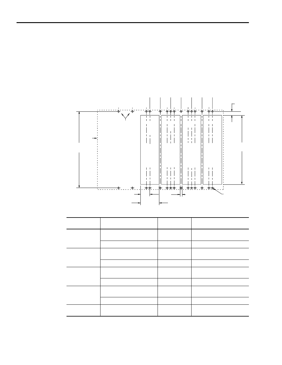
Based on your actual axis module combination, use the following
illustration and table to modify your subpanel using the dimensions
that correspond to that specific combination.
Figure 1.3
1394 Mounting Hole Layout
Note: When mounting axis module combinations, you must mount the 1394x-AM50, -AM75, -AM50-IH, and -AM75-
IH closest to the system module and ahead of the 1394x-AM03, -AM04, and -AM07 axis modules.
Axis Module
Combination
Type of Axis Module
Number of Axes
Cutout Needed?
A
1394x-AM50, or -AM75, and
1394C-AM50-IH, or -AM75-IH
0
no
1394x-AM03, AM04, or AM07
up to 4
no
B
1394x-AM50, or -AM75, and
1394C-AM50-IH, or -AM75-IH
1
yes (1394x-AM50 or -AM75)
no (1394C-AM50-IH or -AM75-IH)
1394x-AM03, AM04, or AM07
up to 3
no
C
1394x-AM50, or -AM75, and
1394C-AM50-IH, or -AM75-IH
2
yes (1394x-AM50 or -AM75)
no (1394C-AM50-IH or -AM75-IH)
1394x-AM03, AM04, or AM07
up to 2
no
D
1394x-AM50, or -AM75, and
1394C-AM50-IH, or -AM75-IH
3
yes (1394x-AM50 or -AM75)
no (1394C-AM50-IH or -AM75-IH)
1394x-AM03, AM04, or AM07
up to 1
no
E
1394x-AM50, or -AM75, and
1394C-AM50-IH, or -AM75-IH
4
yes (1394x-AM50 or -AM75)
no (1394C-AM50-IH or -AM75-IH)
50
(1.97)
0
(0.00)
62.5
(2.46)
50
(1.97)
125
(4.92)
100
(3.94)
137.5
(5.41)
175
(6.89)
200
(7.87)
212.5
(8.37)
225
(8.86)
250
(9.84)
275
(10.83)
287.5
(11.32)
B
C
D
E
B
B
B C
D
E
A
C
C
D
E
D E
19.5
(0.768)
33.5 TYP
(1.32)
67 TYP
(2.64)
8 TYP
(0.32)
M6 tapped hole or
1/4-20 UNC - 2B
385
(15.16)
348
(13.70)
A
A
A
150
(5.91)
System module
mounting holes
Heatsink
cutout for the
AM50/75
module
only
Heatsink
cutout for the
AM50/75
module
only
Heatsink
cutout for the
AM50/75
module
only
Heatsink
cutout for the
AM50/75
module
only
System
outline
Dimensions are in millimeters and (inches)