Ventilation requirements, Ventilation requirements -7, Figure 1.2) f – Rockwell Automation 1394 SERCOS Interface Multi-Axis Motion Control System Installation Manual User Manual
Page 17
Publication 1394-IN002B-EN-P — February 2004
Installing Your 1394 SERCOS Interface System
1-7
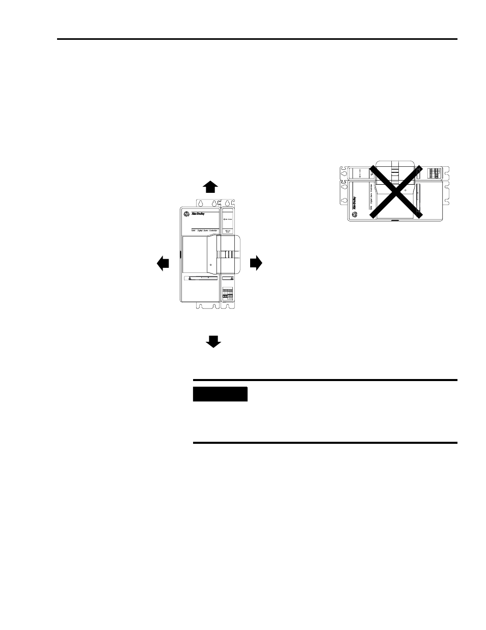
Ventilation Requirements
This section provides information to assist you in sizing your cabinet
and locating your 1394 system components. Refer to Figure 1.2 for
minimum clearance requirements for power rail components mounted
inside the cabinet.
Figure 1.2
Minimum System and Axis Module Mounting Requirements
Refer to Appendix A for 1394 power dissipation specifications.
Status
Status
DANGER
RISK OF ELECTRICAL SHOCK. HIGH VOLTAGE MAY
EXIST UP TO FIVE MINUTES AFTER REMOVING POWER.
D
ANGER
RISK OF ELECTRICAL SHOCK.
HIGH
VOL
TAGE MA
Y
EXIST
UP TO
FIVE
MINUTES AFTER
REMOVING
POWER.
50.8 mm (2.0 in.) clearance
for airflow and installation
Allow additional clearance below the system module to provide the recommended cable bend radius. Refer
to the Motion Control Selection Guide (publication GMC-SG001x-EN-P) for more information.
Allow 10.0 mm (0.4 in.) side clearance
Allow 76.2 mm (3.0 in.) clearance
for depth of terminator.
Wire entry area for cable ground clamps
and signal, power, and motor connections.
Allow 10.0 mm (0.4 in.) side clearance
Allow 25.4 mm (1.0 in.) clearance
at cover tab for opening and closing.
IMPORTANT
If the cabinet is ventilated, use filtered or
conditioned air to prevent the accumulation of dust
and dirt on electronic components. The air should be
free of oil, corrosives, or electrically conductive
contaminates.