Auxiliary feedback connector pin-outs, Auxiliary feedback connector pin-outs -9 – Rockwell Automation 1394 SERCOS Interface Multi-Axis Motion Control System Installation Manual User Manual
Page 41
Publication 1394-IN002B-EN-P — February 2004
1394 SERCOS Interface Connector Data
2-9
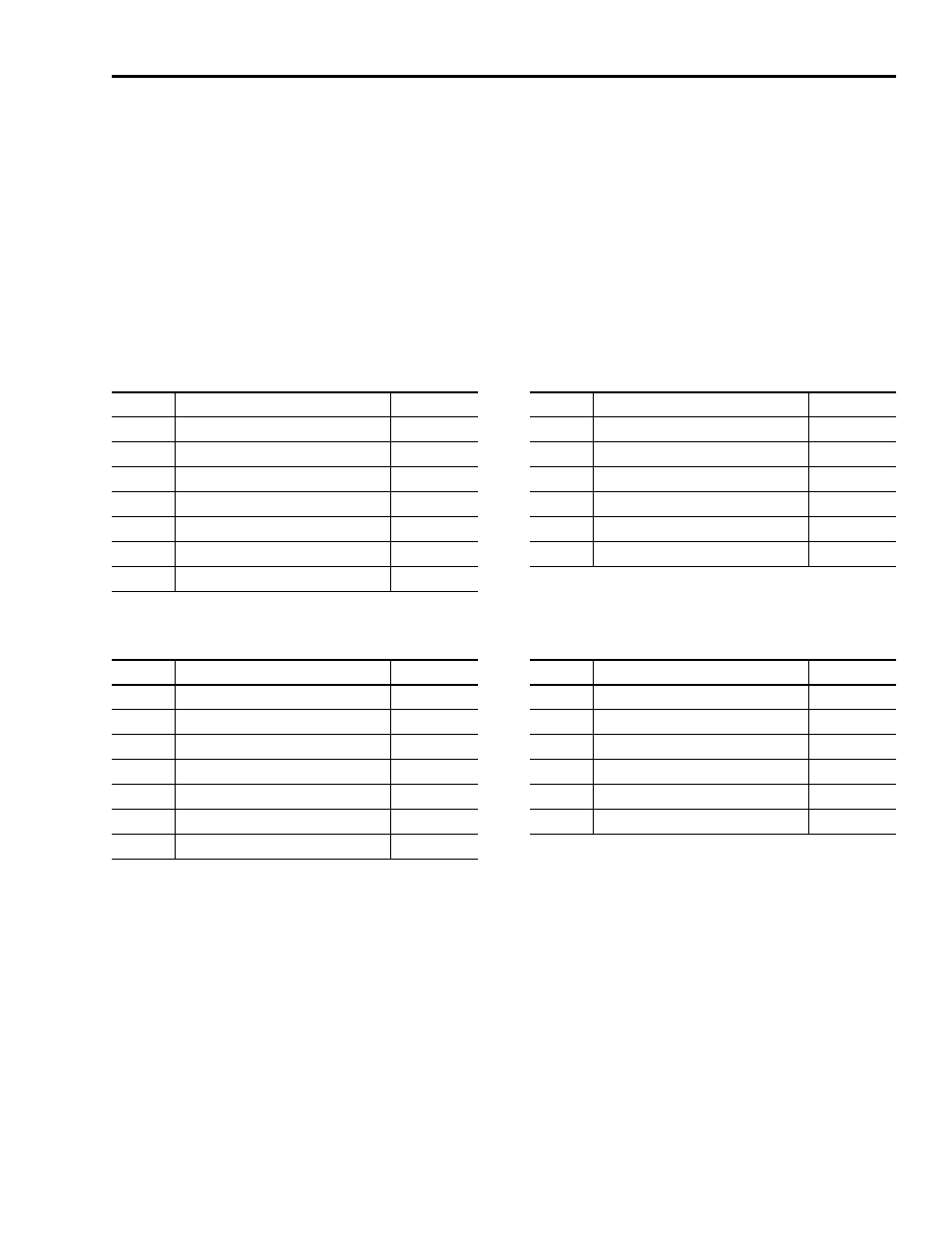
Auxiliary Feedback Connector Pin-outs
The following tables provide the signal descriptions and pin-outs for
the auxiliary feedback (13-pin) connectors when used with different
feedback devices. Motor and Auxiliary Feedback Specifications begin
on page 2-21.
Note: For TTL devices, the position count will increase when A leads
B. For sinusoidal devices, the position count will increase when
cosine leads sine.
Stegmann Hiperface (SRS and SRM)
TTL or Sine/Cosine with Index Pulse
Pin
Description
Signal
Pin
Description
Signal
1
Sine Differential Input+
SINE+
8
Reserved
—
2
Sine Differential Input-
SINE-
9
Reserved
—
3
Cosine Differential Input+
COS+
10
Hiperface data channel
DATA-
4
Cosine Differential Input-
COS-
11
Reserved
—
5
Hiperface data channel
DATA+
12
Reserved
—
6
Common
ECOM
13
Reserved
—
7
Encoder Power (+5V)
EPWR_5V
Pin
Description
Signal
Pin
Description
Signal
1
A+ / Sine Differential Input+
A+ / SINE+
8
Reserved
—
2
A- / Sine Differential Input-
A- / SINE-
9
Reserved
—
3
B+ / Cosine Differential Input+
B+ / COS+
10
Index Pulse-
I-
4
B- / Cosine Differential Input-
B- / COS-
11
Reserved
—
5
Index Pulse+
I+
12
Reserved
—
6
Common
ECOM
13
Reserved
—
7
Encoder Power (+5V)
EPWR_5V