Install components – Rockwell Automation PF700 PowerFlex 700 Drive Components Replacement - Frame 9 User Manual
Page 69
Rockwell Automation Publication 20B-IN025B-EN-P - January 2011
69
Component Replacement Procedures Chapter 3
Install Components
1.
Place Fan assembly into the chassis but not installed in final position. Leave
space for accessing Fan cables from the front of the drive.
Take care to not pinch wires.
2.
From the front of the drive, reconnect Fan cables.
3.
Place Fan assembly in final position in the chassis.
4.
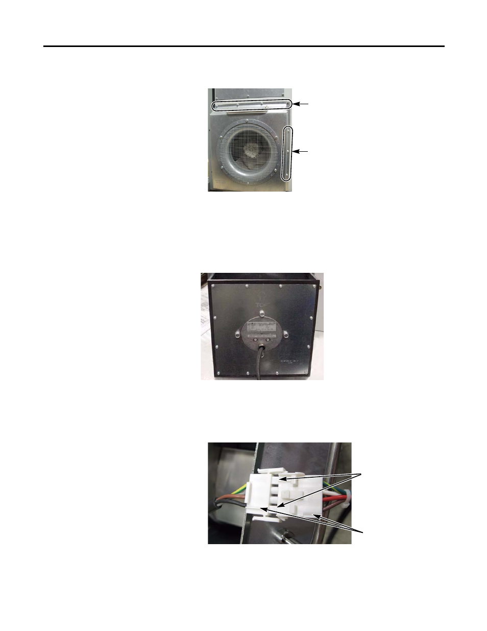
On the back of the drive, install the 11 screws for the Fan cover. Torque to
9.0 N•m (80 lb•in).
TIP
The connectors, one set shown below, are designed so they go
together only one way. The two end sections are flat on one side and
each section has a ridge at the matching edge.
Fan Cover Screw Locations on Back of Drive
4 on top and bottom
for a total of 8
3 on right side
NOTE: No screws on left side
Fan Assembly
(Front View),
Removed from Drive
Ridges
Flat Sections
Connectors shown
slightly separated