Capacitor bank fan, Remove components, Install components – Rockwell Automation PF700 PowerFlex 700 Drive Components Replacement - Frame 9 User Manual
Page 51
Rockwell Automation Publication 20B-IN025B-EN-P - January 2011
51
Component Replacement Procedures Chapter 3
Capacitor Bank Fan
See
Chapter 1 - Drive Components
to locate the component detailed in these
instructions.
Remove Components
1.
Read and follow the
Safety Precautions on page 8
and
Important Initial
Steps on page 10
.
2.
Perform
Remove Main Control Panel on page 22
.
3.
Perform
Remove Stacking Panel on page 25
.
4.
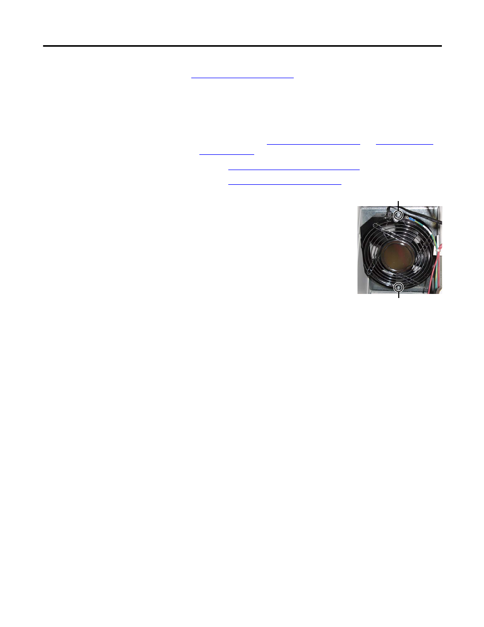
Locate the Capacitor Bank Fan.
5.
Label and disconnect all wires for the fan.
6.
Remove the top and bottom mounting screws.
7.
Remove the fan assembly and dispose of it
properly.
Install Components
1.
Install the new fan assembly. Hand tighten the
two mounting screws.
2.
Reconnect wires.
3.
Torque the two mounting screws to 2.9 N•m (26 lb•in).
4.
Reassemble remaining components in reverse order.
5.
Replace all safety shields and enclosure covers before applying power to the
drive.
Top Fan Mounting Screw
Bottom Mounting Screw is
directly behind this screw