Heatsink fan - removal from back of drive, Remove components – Rockwell Automation PF700 PowerFlex 700 Drive Components Replacement - Frame 9 User Manual
Page 68
68
Rockwell Automation Publication 20B-IN025B-EN-P - January 2011
Chapter 3 Component Replacement Procedures
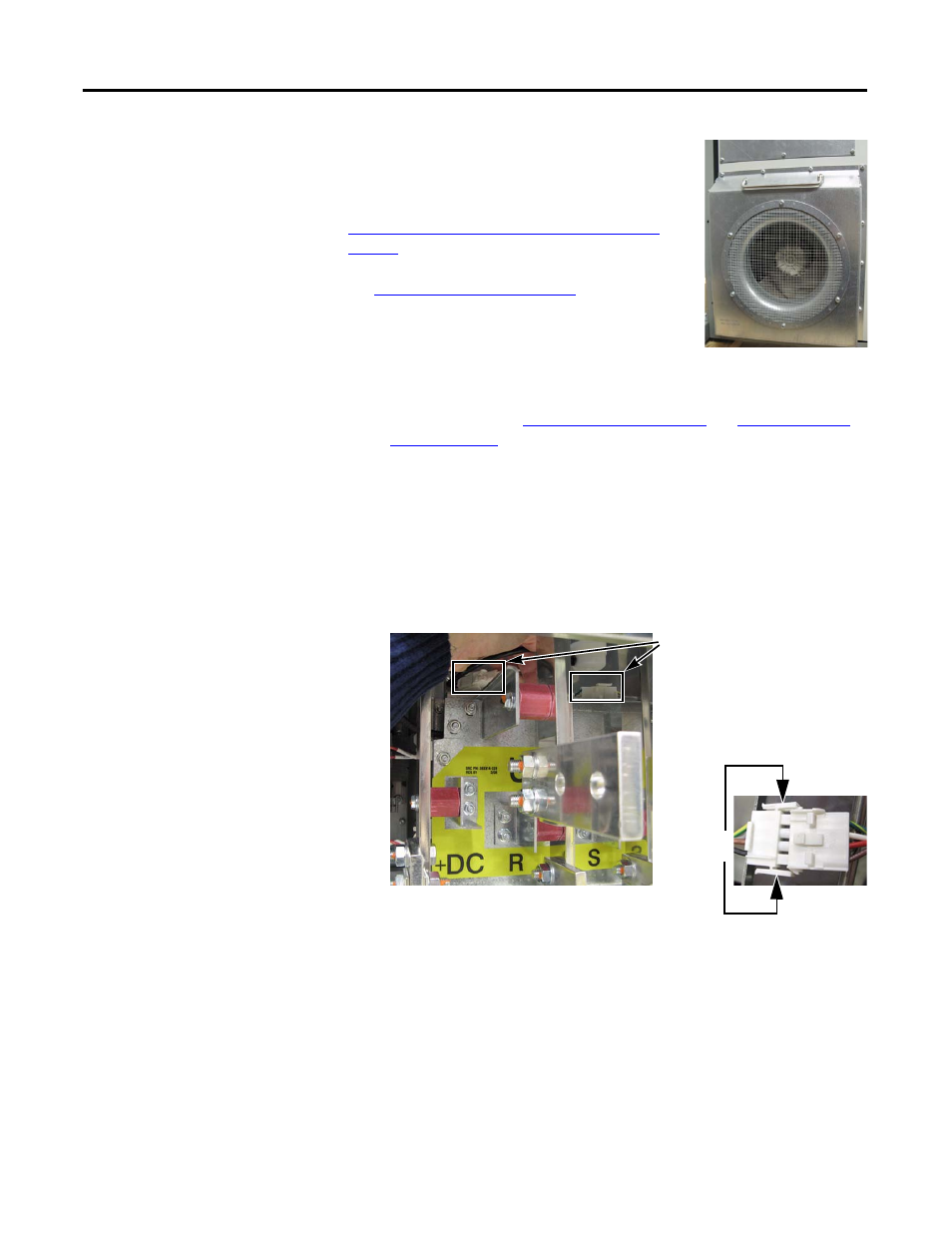
Heatsink Fan - Removal
from Back of Drive
The Heatsink Fan is located on the back of the drive.
(For equipment clearance considerations, the Fan
can also be removed from the front of the drive. See
Heatsink Fan - Removal from Front of Drive on
page 70
.)
See
Chapter 1 - Drive Components
to locate the
component detailed in these instructions.
Remove Components
1.
Read and follow the
Safety Precautions on page 8
and
Important Initial
Steps on page 10
.
2.
Verify that there is at least a 91 cm (3 ft) clearance in back of the drive for
access to the Heatsink Fan.
3.
From the front of the drive, disconnect the cables for the Fan and the Fan
Capacitor.
Access the cables by gently pulling the wiring from behind the busbar
mounting panel.
4.
On the back of the drive, remove the 11 screws for the Fan cover; see the
figure on the next page for the screw locations.
Do not remove the screws for the screen.
5.
Using the handle, separate the Fan assembly from the drive enclosure.
Some force may be needed to separate the Fan from the enclosure as the
gasket may be tight or sticky.
6.
Remove Fan and properly discard.
Disconnect
here
Press tabs in for removal
Front of drive
Connectors