Blower control panel, Remove components, Install components – Rockwell Automation PF700 PowerFlex 700 Drive Components Replacement - Frame 9 User Manual
Page 24
24
Rockwell Automation Publication 20B-IN025B-EN-P - January 2011
Chapter 2 Basic Component Removal Procedures
Blower Control Panel
See
Chapter 1 - Drive Components
to locate the component detailed in these
instructions.
Remove Components
1.
Read and follow the
Safety Precautions on page 8
and
Important Initial
Steps on page 10
.
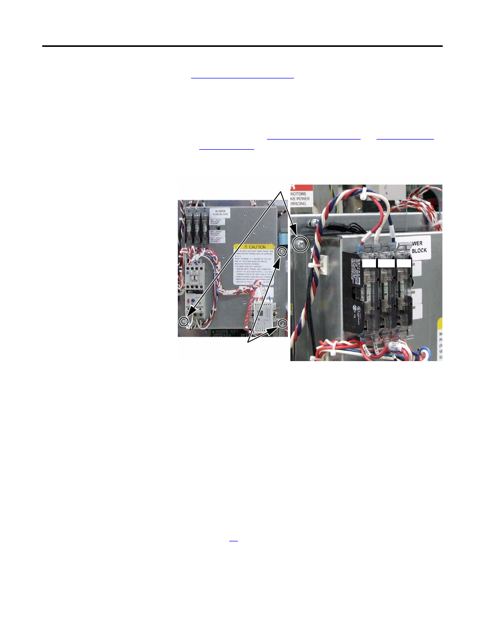
2.
Disconnect the three wires (red, white, and blue) at the top of the blower
fuse block.
3.
Label and remove all wiring to TB9.
4.
Remove the two screws that connect the Blower Control Panel to the
Main Control Panel.
NOTE:
These screws are already removed if the Main Control Panel has
been removed.
5.
Remove the two screws that connect the Blower Control Panel to the
Stacking Panel.
6.
Carefully set the Blower Control Panel aside.
Install Components
1.
When instructed for the component you are replacing, reinstall the Blower
Control Panel in the reverse order of removal.
2.
See page
26
for reinstalling wires to TB9.
3.
Torque panel mounting screws to 2.9 N•m (26 lb•in).
4.
Replace all safety shields and enclosure covers before applying power to the
drive.
Red White Blue
Screws (2) to connect to
Main Control Panel
Screws (2) to connect to Stacking Panel