Current transducer, Remove components – Rockwell Automation PF700 PowerFlex 700 Drive Components Replacement - Frame 9 User Manual
Page 60
60
Rockwell Automation Publication 20B-IN025B-EN-P - January 2011
Chapter 3 Component Replacement Procedures
Current Transducer
See
Chapter 1 - Drive Components
to locate the component detailed in these
instructions.
Remove Components
1.
Read and follow the
Safety Precautions on page 8
and
Important Initial
Steps on page 10
.
2.
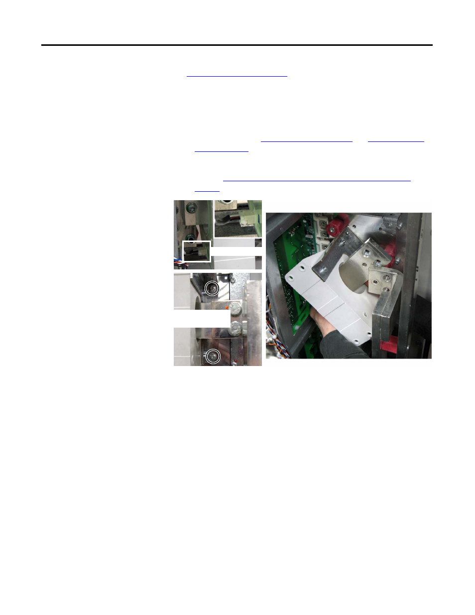
Locate the Current Transducer to be replaced.
3.
Perform
Remove the Output Busbar at the Current Transducer: on
page 54
.
4.
Remove the two torx screws that secure the Current Transducer assembly
(transducer and brackets) to the chassis.
5.
Rotate the Current Transducer assembly counterclockwise and tip until
the Output Busbar clears the U, V, or W Busbar and spacer.
NOTE:
Avoid any contact with the circuit board to the left of the
transducer being removed.
6.
Move the busbar and transducer to an ESD-safe flat surface for working
with it.
7.
Separate the Output Busbar from the Current Transducer.
8.
Separate the Current Transducer from the brackets.
9.
Properly discard the Current Transducer.
Wire to Transducer
Transducer Assembly
Torx Screws (2)