Install components – Rockwell Automation PF700 PowerFlex 700 Drive Components Replacement - Frame 9 User Manual
Page 42
42
Rockwell Automation Publication 20B-IN025B-EN-P - January 2011
Chapter 3 Component Replacement Procedures
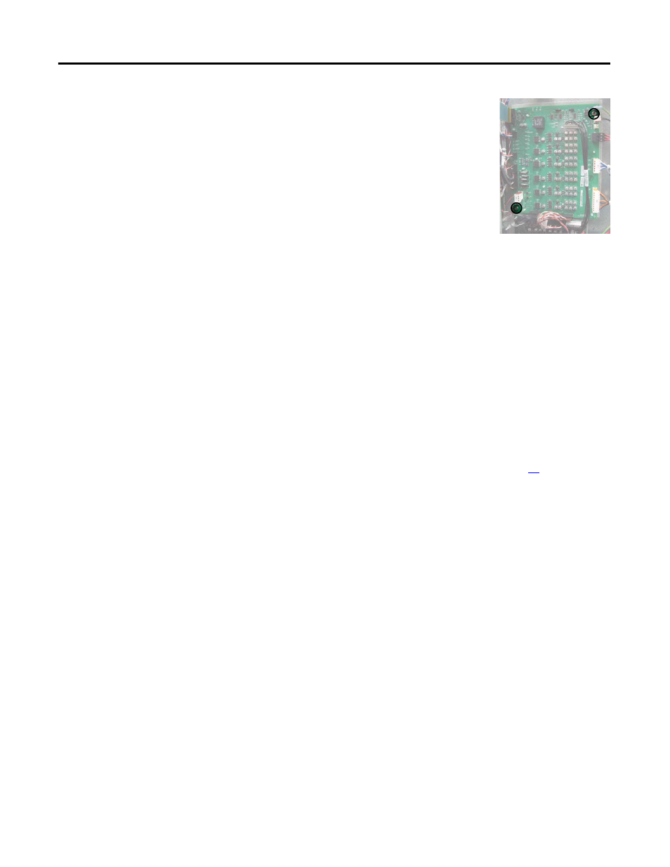
4.
Remove the two mounting torx screws located
at the upper right and lower left corners of the
board as shown at right.
5.
Using your fingers or needle-nose pliers,
squeeze the tabs of each of the nine spacers (see
previous page for their locations), and separate
the Power Interface Board from the mounting
plate.
6.
Remove the Power Interface Board; return or
dispose of it properly.
Install Components
1.
Install the new Power Interface Board.
Tighten board screws to 1.7 N•m (15 lb•in).
2.
Reconnect all wiring as detailed in the Table on the previous page.
3.
Reconnect the Main Control Board wires to TB1 and TB2 on the Power
Interface Board.
Tighten sheet metal screws to 3.2 N•m (28 lb•in).
4.
Reconnect the ribbon cable going from the Power Interface Board ( J1) to
the Main Control Board ( J2).
5.
Reinstall the Main Control Board as instructed on page
22
.
6.
Replace all safety shields and enclosure covers before applying power to the
drive.