Rockwell Automation PF700 PowerFlex 700 Drive Components Replacement - Frame 9 User Manual
Page 30
30
Rockwell Automation Publication 20B-IN025B-EN-P - January 2011
Chapter 2 Basic Component Removal Procedures
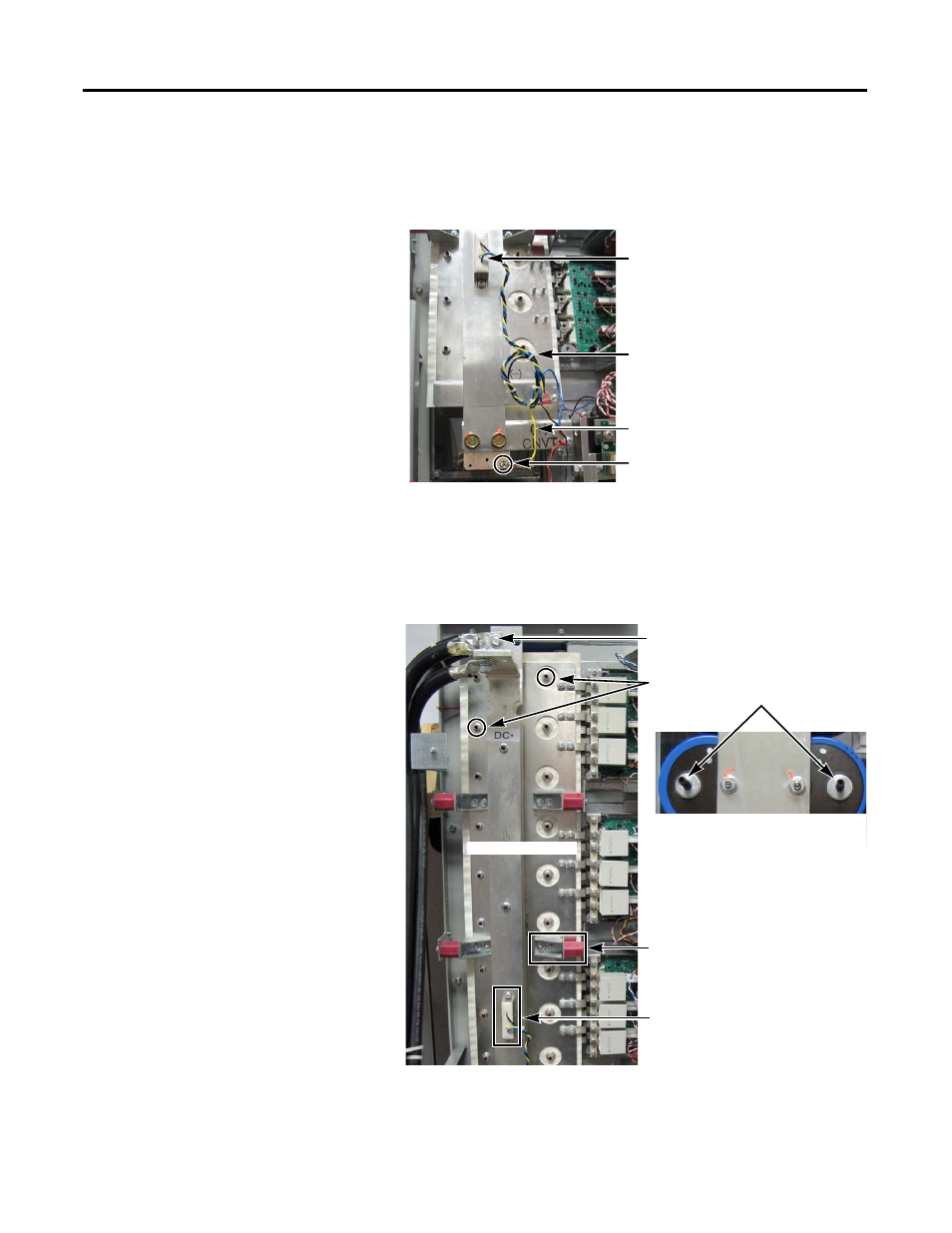
10.
Cut tie wraps for the Balancing Resistor wiring.
11.
Disconnect the yellow wire for the Balancing Resistor.
You do not need to disconnect the blue and black wires.
12.
Remove the four side standoffs and brackets for the Transitional Busbar
assembly.
13.
Remove the 18 nuts fastening the Transitional Busbar assembly to the Bus
Capacitors.
Setscrews may come out with the nuts. Save all nuts and setscrews.
Balancing Resistor
Balancing Resistor yellow wire
Disconnect here
Resistor wiring tie wraps
Transitional Busbar Nuts (18)
attached to Setscrews
Side Standoffs and Brackets (4)
DC Choke Output Cables
Balancing Resistor
Transitional Busbar
Photo shows Setscrews in
Capacitors; these Setscrews may come
out with the Transitional Busbar nuts
when they are removed.