Main control panel, Remove components – Rockwell Automation PF700 PowerFlex 700 Drive Components Replacement - Frame 9 User Manual
Page 22
22
Rockwell Automation Publication 20B-IN025B-EN-P - January 2011
Chapter 2 Basic Component Removal Procedures
Main Control Panel
See
Chapter 1 - Drive Components
to locate the component detailed in these
instructions.
Remove Components
1.
Read and follow the
Safety Precautions on page 8
and
Important Initial
Steps on page 10
.
2.
Remove safety shields as needed.
3.
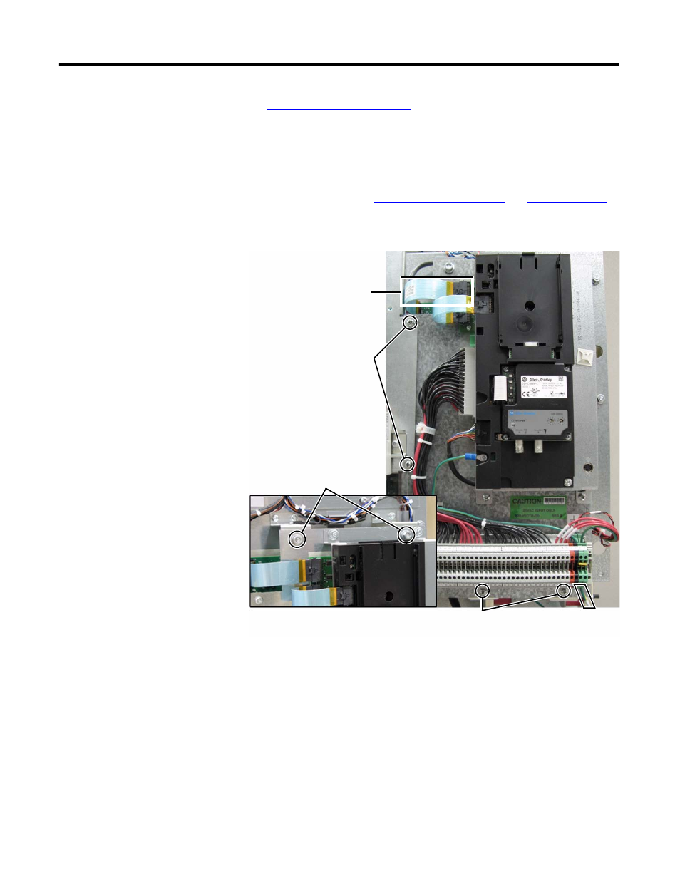
Remove the ribbon cable going from the Main Control Board ( J2) to the
Power Interface Board ( J1).
4.
Disconnect the incoming ground wire to TB11.
5.
Remove the two mounting screws below TB11.
6.
Remove the two screws that adjoin the Blower Control Panel to the Main
Control Panel. These screws are larger than the two removed from below
TB11 so do not mix the two sets.
7.
Remove the two mounting nuts above the Main Control Board.
8.
Remove Main Control Panel; support.
Ribbon Cable from Main Control
Board to Power Interface Board
Mounting Screws (2) that adjoin
Blower Control Panel to
Main Control Panel
Mounting Nuts (2) at top of
Main Control Panel
Ground Wire
to TB11
Mounting Screws (2)
below TB11