Remove components – Rockwell Automation PF700 PowerFlex 700 Drive Components Replacement - Frame 9 User Manual
Page 54
54
Rockwell Automation Publication 20B-IN025B-EN-P - January 2011
Chapter 3 Component Replacement Procedures
Remove Components
1.
Read and follow the
Safety Precautions on page 8
and
Important Initial
Steps on page 10
.
2.
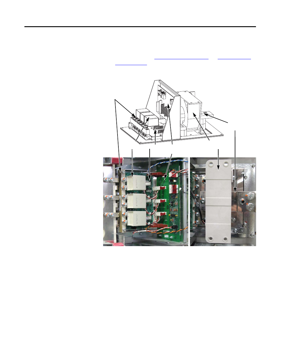
Locate the Inverter Power Module to be replaced.
3.
Remove the Output Busbar at the Current Transducer:
a. Remove and save the torx head bolt that secures the Output Busbar to
the AC Output Busbar.
b. Remove and save the two hex head bolts that secure the Output Busbar
to the U, V or W Busbar.
c. Remove and save the nut and setscrew for the Output Busbar standoff.
d. Slide the Output Busbar to the right as far as it goes.
4.
Remove the AC Output Busbar:
a. Remove and save the six torx screws and two standoff nuts that secure
the AC Output Busbar to the IGBT.
b. Remove and save the two nuts that secure the AC Output Busbar to the
standoffs.
c. Remove and save the AC Output Busbar.
Gate Interface
Board Assembly
Tie Down
Capacitor Mount
Snubber
Capacitors
AC Output
Busbar
Current
Transducer
IGBT