Converter power module (scr) - ac input only, Remove components – Rockwell Automation PF700 PowerFlex 700 Drive Components Replacement - Frame 9 User Manual
Page 62
62
Rockwell Automation Publication 20B-IN025B-EN-P - January 2011
Chapter 3 Component Replacement Procedures
Converter Power Module
(SCR) - AC Input Only
See
Chapter 1 - Drive Components
to locate the component detailed in these
instructions.
Remove Components
1.
Read and follow the
Safety Precautions on page 8
and
Important Initial
Steps on page 10
.
2.
Perform
Remove Main Control Panel on page 22
.
3.
Perform
Remove Stacking Panel on page 25
.
4.
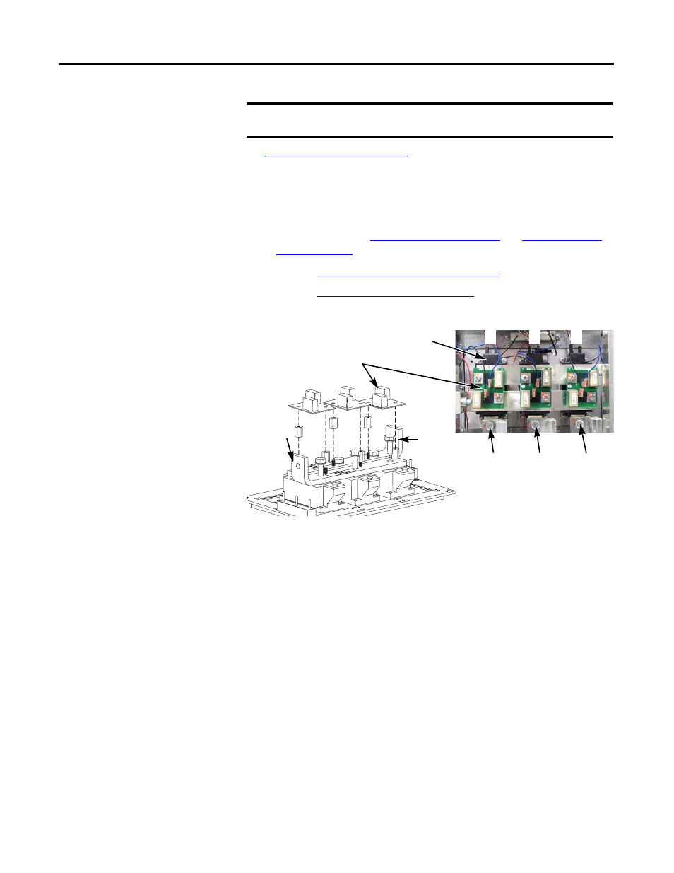
Locate the Converter SCR modules (R, S, T) to be replaced.
5.
Remove all three Converter Snubber Boards:
a. Disconnect the wires between each Converter Snubber Resistor and
Converter Snubber Board.
b. Remove the two screws that secure each board.
c. Remove each board and set aside.
6.
Note the orientation of the Converter Busbars and remove the eight bolts
that secure the busbars to the SCR modules and to the DC+ and DC-
Busbars. Set the Converter Busbars aside.
7.
Remove the bolt at the top of each AC Busbar (R, S, T) where they
connect to the SCR modules.
You do not need to remove the wires from the AC Busbars.
8.
Label and note the position of the SCR module leads. Remove the leads.
Typically, the leads are marked as R, S, or T, and each is notched with the
notch to the front of the SCR module.
9.
Remove the four Phillips screws that hold each SCR to the Heatsink.
10.
Remove the SCR modules; return or dispose of them properly.
IMPORTANT
If any Converter SCR module fails, all three SCR modules should be
replaced (kit includes all three modules).
R
S
T
Converter Snubber Boards (3)
Converter SCR Modules (3)
R
S
T
Converter
Busbar,
Lower (+DC)
Converter
Busbar,
Upper (-DC)
AC Busbar
(R) Bolt
AC Busbar
(S) Bolt
AC Busbar
(T) Bolt