Chapter 3: component replacement procedures, Overview, Main control board – Rockwell Automation PF700 PowerFlex 700 Drive Components Replacement - Frame 9 User Manual
Page 35: Remove components, Chapter 3, Overview main control board, Component replacement procedures, Chapter
Rockwell Automation Publication 20B-IN025B-EN-P - January 2011
35
Chapter
3
Component Replacement Procedures
Overview
Component procedures detailed in this chapter apply to PowerFlex 700 Frame 9
drives for AC or DC input. Removal and replacement instructions for the Stacking
Panel and Transitional Bar assemblies are detailed in Chapter 2.
Main Control Board
See
Chapter 1 - Drive Components
to locate the component detailed in these
instructions.
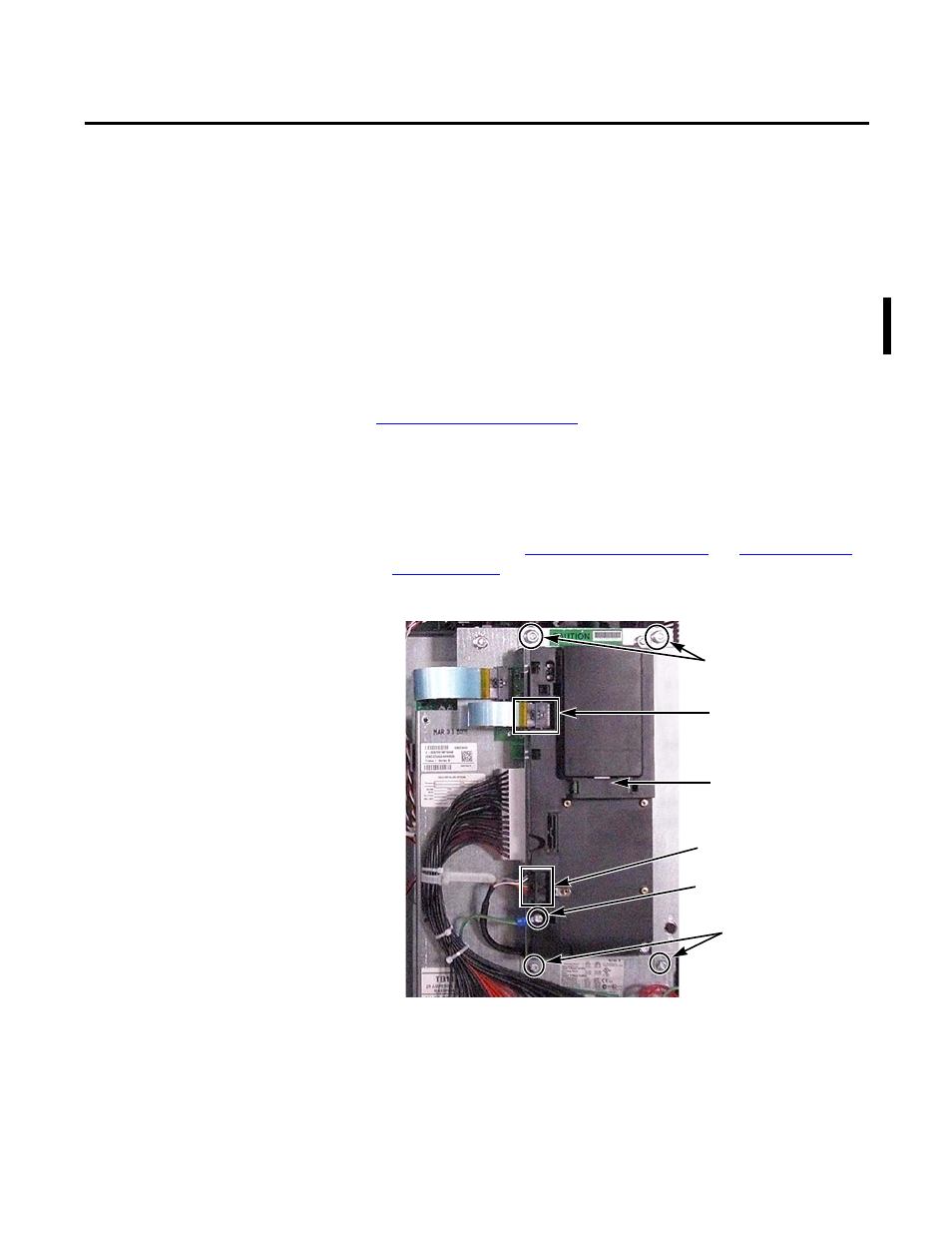
Remove Components
1.
Read and follow the
Safety Precautions on page 8
and
Important Initial
Steps on page 10
.
2.
Remove safety shields as needed.
3.
Unscrew the green/yellow ground wire from the Communications Panel.
4.
Remove the nuts, screws and washers (two each) that secure the
Communications Panel to the Main Control Panel.
5.
Disconnect the ribbon cable that connects the HIM Cradle/Board to the
Main Control Board.
Screw for green/yellow
Ground Wire
Cable at DPI Port 2 Clamp
Communication Panel
Mounting Nuts (2)
Communication Panel
Mounting Screws and
Washers (2 each)
HIM Cradle/Board
(Located over
Main Control Panel)
Ribbon Cable
from HIM Cradle/Board
to Main Control Board