Rockwell Automation PF700 PowerFlex 700 Drive Components Replacement - Frame 9 User Manual
Page 57
Rockwell Automation Publication 20B-IN025B-EN-P - January 2011
57
Component Replacement Procedures Chapter 3
4.
Reinstall the Transitional Busbar as instructed on page
32
.
5.
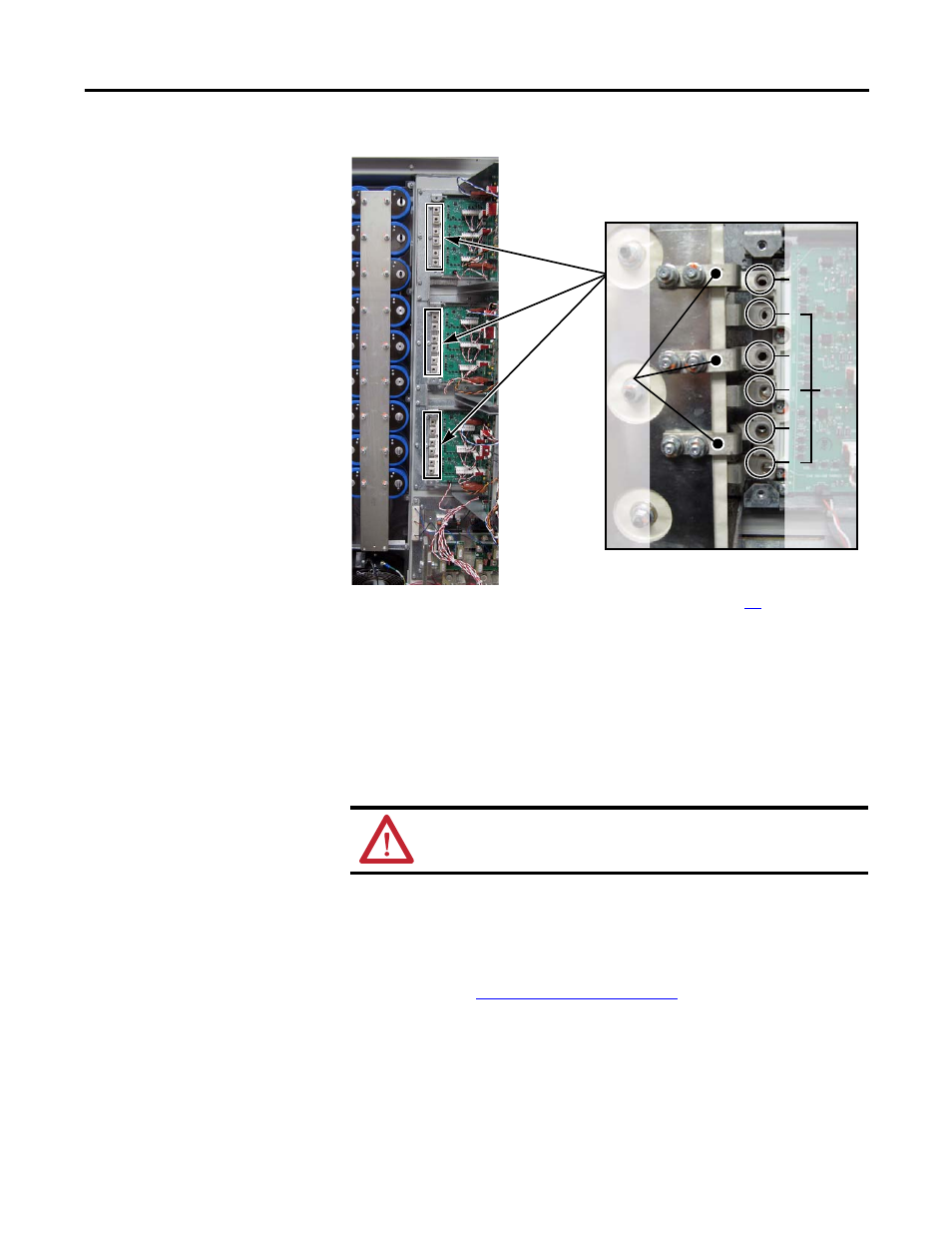
Install the three supplied negative (DC-) Flexible Capacitor Busbars in
positions 1, 3, and 5 on the IGBT.
The negative (DC-) Flexible Capacitor Busbars have a higher angle.
6.
Install the Tie Down Capacitor Mount:
a. Insert the short ends of the six threaded studs with nuts through the
Flexible Capacitor Busbars and into the left side of the IGBT. Torque to
5.6 N•m (50 lb•in).
b. Install the Tie Down Capacitor Mount with the two screws previously
removed from the top and bottom of the Capacitor Mount. Torque to
2.9 N•m (26 lb•in).
7.
Install the Current Transducer, AC Output Busbar, and Output Busbar
according to
.
WARNING: Correct torque is critical to ensure correct operation
of the drive. Improper torquing could cause premature failure when
attempting to operate the drive.
Posi
ti
ve
(DC+) Fl
exi
ble Capacitor Busbars
Shown with Transitional Busbar and
all Flexible Capacitor Busbars installed
1
2
3
4
5
6
Negative (DC-) F
lex
ib
le Ca
pa
cit
or Bu
sb
ar
s