Bump, Bump 30 – RKI Instruments Gas Tracer User Manual
Page 80
72 • Calibration Mode
Gas Tracer Operator’s Manual
3. Install the hose and probe to the Gas Tracer.
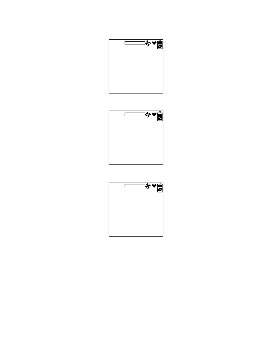
4. Use the AIR▲ or (SHIFT)▼ buttons to display the BUMP menu
item.
5. Press and release the POWER ENTER button to display the bump
test gas values.
6. Use the AIR▲ or (SHIFT)▼ buttons to see the %volume
combustible gas bump test value.
7. A bump test may be performed on the standard 3 sensors or on the
%volume combustible sensor. Use the AIR▲ or (SHIFT)▼ buttons
to display the screen of sensor(s) you wish to bump test.
8. Before proceeding, confirm that the bump test gas value(s) are the
same as the concentration(s) in the calibration cylinder. If they are
not, adjust the bump test gas value(s) by entering the AUTO CAL
menu item, changing the values there, and reentering the BUMP
menu.
9. Connect the tubing from the demand flow regulator to the rigid
tube on the probe then quickly press and release the POWER
MAINTENANCE
BUMP
50
12.0
50
%LEL
%
ppm
MAINTENANCE
CH
4
O
2
BUMP 30
CO
100
vol%
MAINTENANCE
CH
4
BUMP 30