Warning – MacDon D60 Draper Headers User Manual
Page 46
SECTION 7. OPERATION
Form 169441
44
Revision B
7.12.9.1 Mechanical Adjustment - Fore-Aft
WARNING
Stop windrower engine, and remove key
before making adjustments to machine. A
child or even a pet could engage the drive.
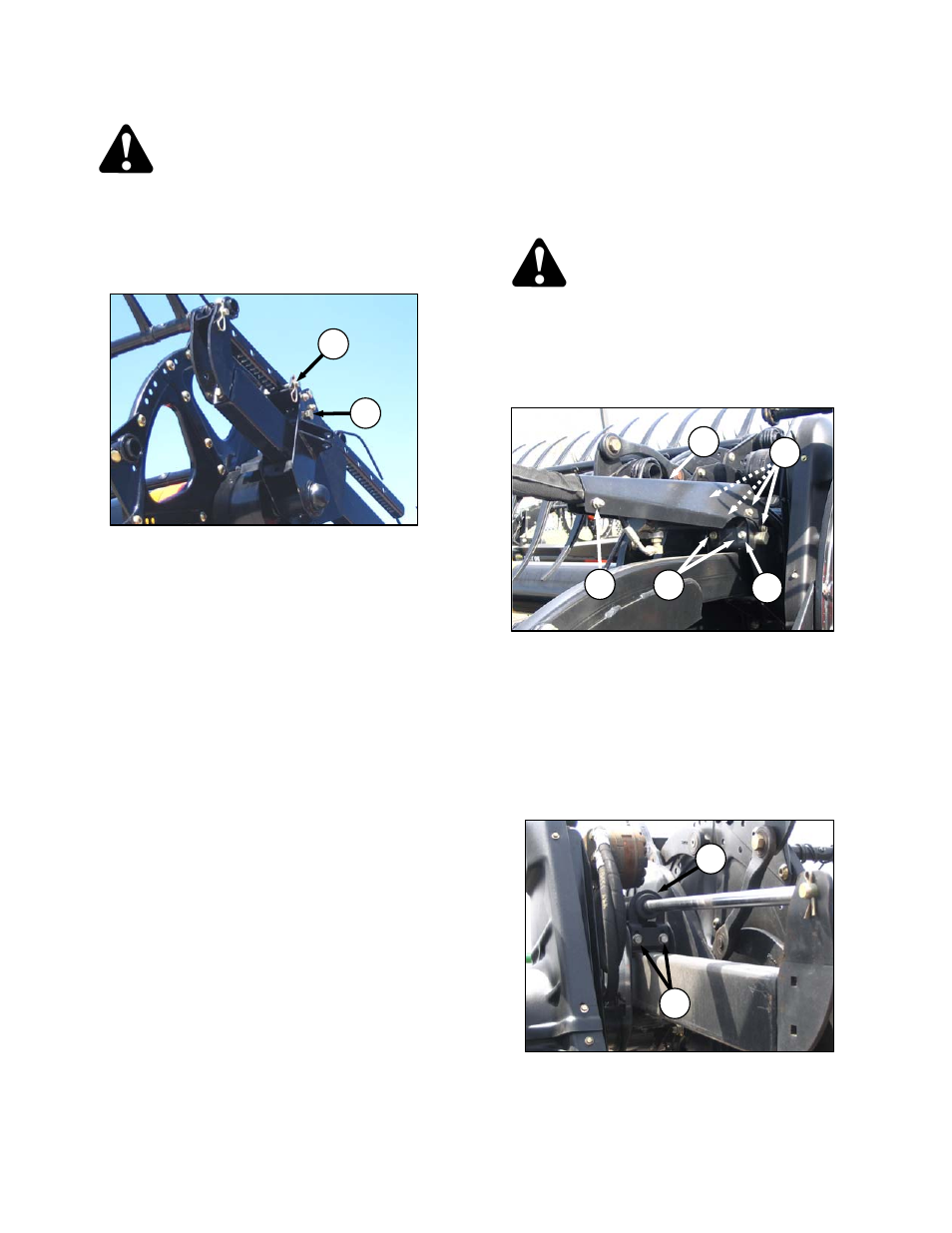
a. Lower or raise reel so support arms are
horizontal, stop engine, and remove key.
b. Remove pin (A) at each support arm.
c. Using a 15/16 in. wrench on bolt (B) turn sprocket
inside reel arm to slide reel to the desired
position. If reel binds on arms from misalignment,
move in smaller increments (two holes at a time).
d. Re-install pin (A). Be sure the same hole is used
at each arm.
e. Check that the reel is evenly adjusted.
f. Check reel clearance to cutterbar after making
changes to cam setting. Refer to Section 8.9.1
Reel Clearance to Cutterbar and, 8.9.2 Reel
Frown Adjustment for measurements and
adjustment procedures.
7.12.9.2 Hydraulic Adjustment - Fore-Aft
a. Select the fore-aft adjust mode on the selector
switch in the cab (if applicable).
b. Operate the hydraulics to move the reel to the
desired position, again using the gauge as a
reference.
c. Check reel clearance to cutterbar after making
changes to cam setting. Refer to Section 8.9.1
Reel Clearance to Cutterbar and, 8.9.2 Reel
Frown Adjustment for measurements and
adjustment procedures.
7.12.9.3 Fore-Aft Cylinder Position
The reel can be moved approximately nine inches
further aft by re-positioning the cylinders on the
reel arms.
a. Position reel so support arms are horizontal, stop
engine, and remove key.
WARNING
Stop windrower engine, and remove key
before making adjustments to machine. A
child or even a pet could engage the drive.
b. Re-position center arm cylinder (Double Reel) as
follows:
1. Remove bolt and nut (C), and four bolts (D)
securing hose shield (E) on center arm
(applicable to double reel only).
2. Move hose shield and hoses away from
cylinder.
3. Remove bolts (F) that secure aft support
plate (G), and remove the plate.
4. Remove bolts (H), so that front support plate
(J) is free to move up.
(continued next page)
A
B
F
G
E
CENTER ARM - AFT
D
C
CENTER ARM - FRONT
J
H