MacDon D60 Draper Headers User Manual
Page 25
SECTION 7. OPERATION
Form 169441
23
Revision B
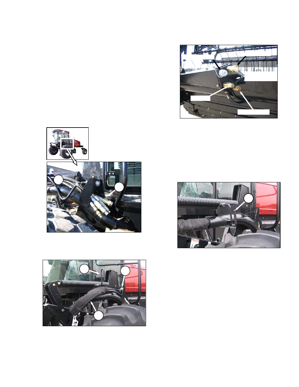
7.3 HEADER
ATTACHMENT/DETACHMENT
7.3.1 ATTACHMENT
Refer to the M150/M200 or M205 Self-Propelled
Windrower Operator’s Manual for procedures to
mechanically attach the header to the self-
propelled windrower. Refer to the following
procedures for electrical and hydraulic
connections.
The header drive hydraulic hoses and electrical
harness are located on the left cab-forward side
of the tractor. The reel drive and control hoses
are located on the right cab-forward side.
a. Connect header drive hydraulics (A) and
electrical harness (B) to header as follows:
1. Check connectors, and clean if required.
2. Disengage and rotate lever (C) counter
clockwise to fully “up” position.
3. Remove cap (D) securing electrical
connector to frame.
4. Move hose bundle (A) from tractor around
hose support on header.
5. Push hose connectors onto mating
receptacle until collar on receptacle snaps
into “lock” position.
6. Remove cover on electrical receptacle.
7. Push electrical connector onto receptacle,
and turn collar on connector to lock it in
place.
8. Attach cover to mating cover on tractor wiring
harness.
9. Lower lever (C), and engage in “down”
position.
(continued next page)
KNIFE DRIVE
DRAPER DRIVE
RETURN
CASE DRAIN
(DOUBLE KNIFE)
ELECTRICAL
C
A
D
C
B
A