Engine wiring diagram – Multiquip AP6 Series User Manual
Page 81
AP6/AP8 SERIES TRASH PUMPS • OPERATION AND PARTS MANUAL — REV. #0 (06/11/14) — PAGE 81
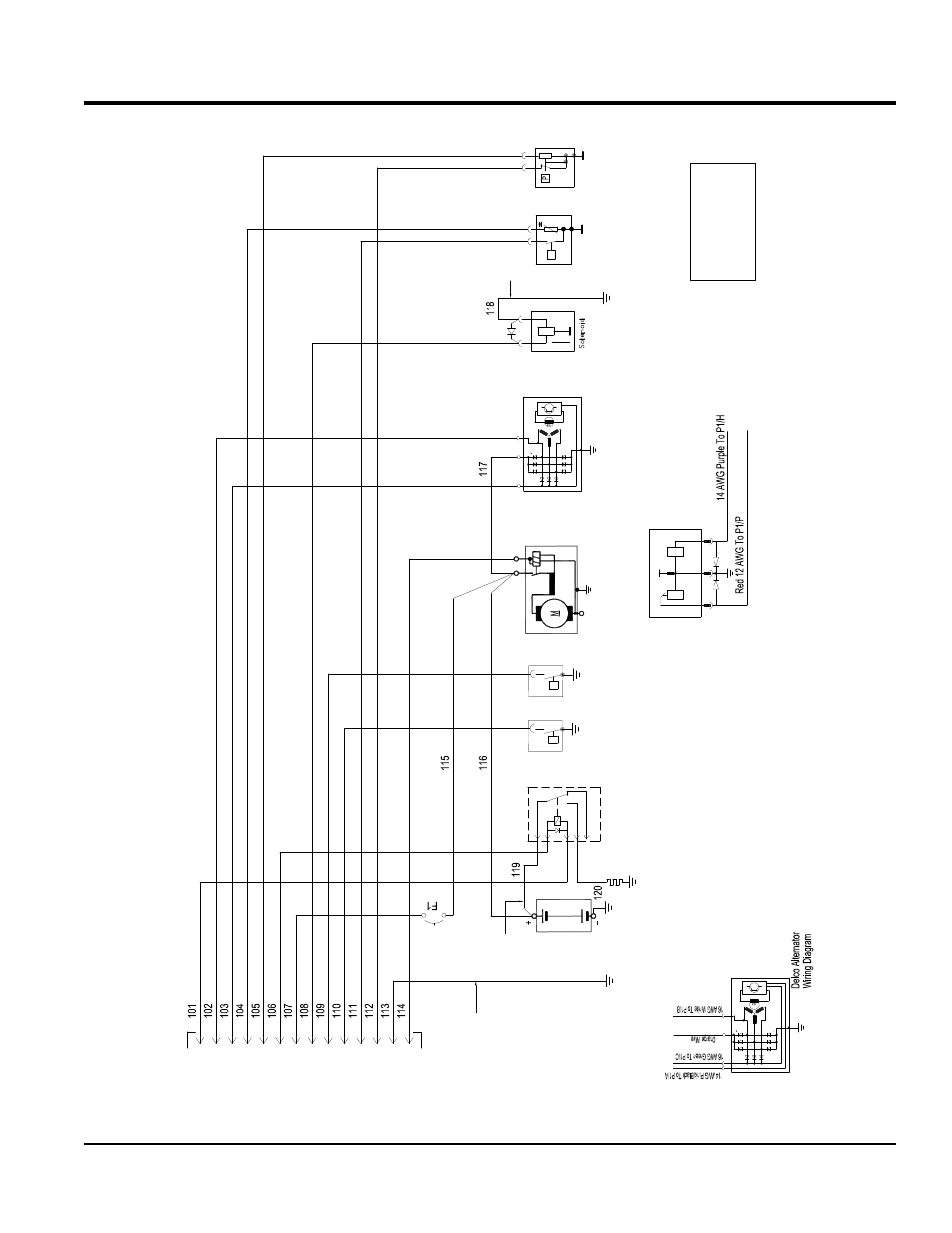
ENGINE WIRING DIAGRAM
C
R
1
P
ow
er
R
el
ay
87
a
30
85
86
87
B
A
T1
B
att
er
y
TAS1
Te
m
pe
ra
tu
re
S
end
er
/S
w
itc
h
W
K
G
PS1 O
il
P
re
ss
ur
e
S
ende
r/S
w
itc
h
W
K
G
P
rehea
t
U
ni
t
G
roun
d
S
O
L3
S
hu
td
ow
n
S
ol
en
oi
d
N
./O
.
N
./C
.
A
LT
1
D
+
B
+
W
M
O
T1
30
50
31
1
2
B
+
R
Pul
l
Hold
3
W
ire
S
ol
en
oi
d
W
iri
ng
D
ia
gr
am
N
ot
e:
-W
K
=
S
w
itc
h
-G
=
G
aug
e
S
W
1
A
ux
1
S
hu
td
ow
n
S
W
2
A
ux
2
S
hu
td
ow
n
In
di
ca
to
rO
nl
y
P1
G
t1
4
P
os
.M
al
e
A
B
C
D
E
F
G
H
J
K
L
M
N
P
Acc
ess
or
y
(1
5)
Ta
cho
m
et
er
D
+
Al
te
rn
at
or
Te
m
p
G
au
ge
Pr
ess
ur
e
G
au
ge
Pr
ehe
at
C
on
tro
l
Ba
tte
ry
+
(3
0)
So
le
no
id
Au
x
S
w
itc
h
2
Au
x
S
w
itc
h
1
Te
m
p
Sw
itc
h
Pr
ess
ur
e
Sw
itc
h
G
rou
nd
St
ar
te
r(
50
)
16
A
W
G
W
hi
te
16
A
W
G
G
ree
n
16
A
W
G
Bl
ue
16
A
W
G
O
ra
ng
e
14
A
W
G
P
ur
pl
e
16
A
W
G
Y
el
lo
w
/B
la
ck
16
A
W
G
Y
el
lo
w
16
A
W
G
Y
el
lo
w
/B
lu
e
16
A
W
G
Y
el
lo
w
/O
ra
ng
e
12
A
W
G
R
ed
/B
la
ck
12
A
W
G
R
ed
8
A
W
G
R
ed
8
A
W
G
R
ed
12
AW
G
R
ed
16
AW
G
Ta
n
16
AW
G
Bl
ac
k
14
AW
G
Pi
nk
/B
la
ck
16
A
W
G
R
ed
16
AW
G
B
la
ck