Operation (auto mode) – Multiquip AP6 Series User Manual
Page 38
PAGE 38 — AP6/AP8 SERIES TRASH PUMPS • OPERATION AND PARTS MANUAL — REV. #0 (06/11/14)
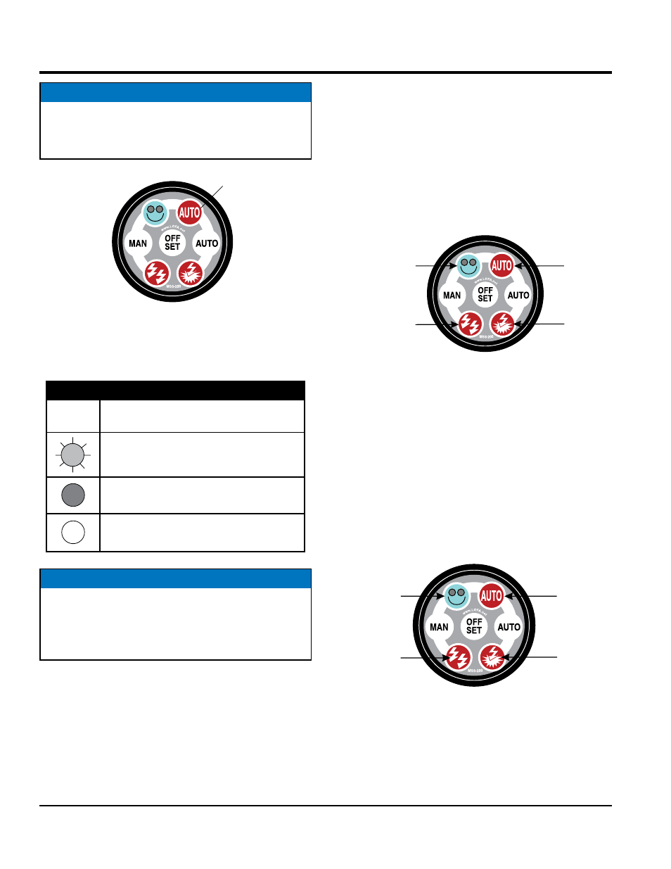
Figure 30. Auto LED Blinking/OFF
LED Status
Table 10 shows the status of the LED's when programming.
NOTICE
A blinking
AUTO LED (Figure 30) during power up
indicates that the
auto start input was activated and
prevents the engine from starting.
AUTO LED FLASHING OR OFF
ENGINE WILL NOT START
Table 10. LED Definitions
LED
Status
Description
Indicates a
flashing LED and identifies
the parameter being programmed.
Indicates LED is
ON, and identifies the
value of the parameter.
Indicates LED is
OFF.
NOTICE
There are 15 programmable parameters (Table 11).
These parameters can be displayed on the controller
in a binary pattern. Reference Table 12 (Programming
Guide) on how to program the parameters.
OPERATION (AUTO MODE)
Controller Display
The controller display face has 4 LEDs. Each LED has a
dual function. Function number 1 is to display the indicated
parameter Function number 2 is to display the set value of
the indicated parameter.
Example Function 1
As shown in Figure 31, parameter 6 (
cool-down cycle)
has been selected LEDs 2 and 4 are blinking.
Figure 31. Parameter 6 Selection
Example Function 2
The cool-down cycle now needs to have a time duration
(0~900 seconds) programmed into the controller. To
accomplish this press the
AUTO button on the controller
until 2 bottom LEDs are on (Figure 32).
This produces a value of 3. This value multiplied by 60
(reference Table 12, engine cool-down) produces a total
cool-down duration period of 300 seconds (5 minutes).
Press the OFF/SET button to enter the value into the
controller.
Figure 32. Parameter 6 Value
1 (OFF)
8 (OFF)
(BLINKING) 2
(BLINKING) 4
1 (ON)
8 (OFF)
(ON) 2
(OFF) 4