Float switches (auto mode), Mechanical float switch, How it works – Multiquip AP6 Series User Manual
Page 26: Pumping range, Design features
PAGE 26 — AP6/AP8 SERIES TRASH PUMPS • OPERATION AND PARTS MANUAL — REV. #0 (06/11/14)
FLOAT SWITCHES (AUTO MODE)
Mechanical Float Switch
For unattended operation of the pump two mechanically
activated float switches will be required. These float
switches can be connected directly to EP250 control box
via a 4-pin connector located at the rear of the control box.
When the pump is placed in
AUTO mode, the float switches
will allow the pump to start and stop depending on the
length of the tether.
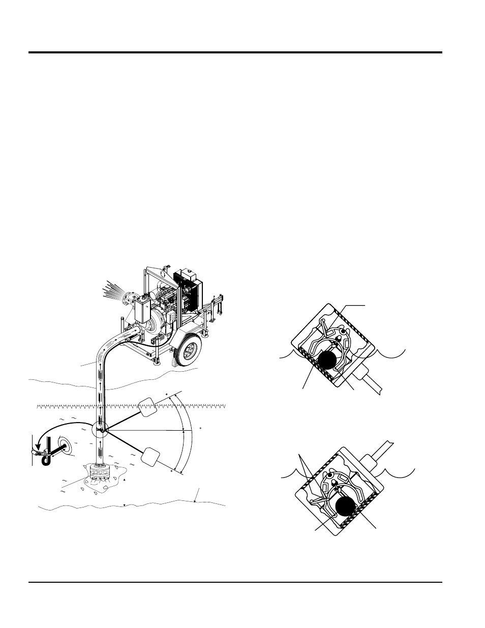
How It Works
The mechanical float switch control will turn
ON (closes)
when the float tips 45° above horizontal, indicating a high
level. It turns
OFF (opens) when the float switch drops
45° below horizontal. Reference Figure 12 and Figure 13.
Maximum pumping range is 120 degrees. See Figure 11
below.
Figure 11. Pumping Range (Float Switch)
SUCTION HOSE
STRAINER
BOTTOM
SURFACE
DO NOT LAY
STRAINER ON
BOTTOM SURFACE
PUMP
ON
60
60
120
PUMP
OFF
3.5 in. (9 cm.)
MINIMUM
TETHER
LENGTH
Pumping Range
The pumping range of the pump is determined by the float
switch tether cord. Use Table 7 as guide line to determine
your required pumping range. Pumping ranges are based
on non-turbulent conditions. Range may vary due to water
temperature and cord shape. Please note as the tether
length increases, so does the variance of the pumping
range.
Design Features
Float switch housings are constructed of high-impact,
corrosion resistant polypropylene with mechanically
activated, snap action contacts.
Suitable for most liquid environments.
Hermetically sealed.
Thick-walled non-corrosive PVC plastic enclosure.
Pressure tested to 30 ft. (9 meters).
Standard SJO, 16-gauge, 2 conductor cord (20 ft./6.09 m).
Figure 12. Float Switch (Closed)
Figure 13. Float Switch (Open)
ON/OFF
RAMP
STEEL
BALL
CONTACTS
CLOSED
ON/OFF
RAMP
STEEL
BALL
CONTACTS
OPEN