Engine control box components – Multiquip AP6 Series User Manual
Page 24
PAGE 24 — AP6/AP8 SERIES TRASH PUMPS • OPERATION AND PARTS MANUAL — REV. #0 (06/11/14)
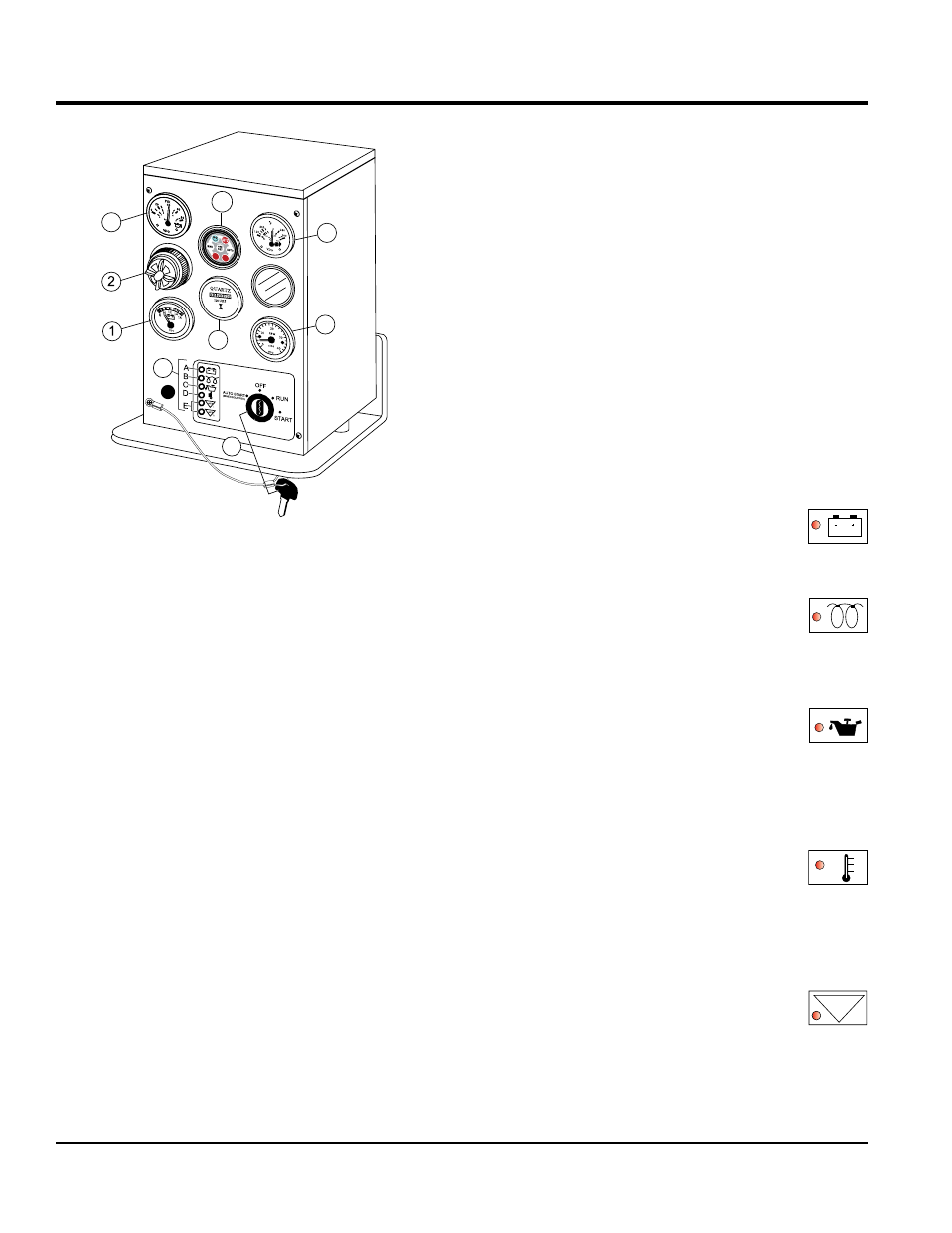
ENGINE CONTROL BOX COMPONENTS
Figure 9. EP250 Control Box
8
9
3
4
5
6
7
Figure 9 shows the location of the components for the
engine control box. The function of each component is
described below:
1.
Voltmeter Gauge – Indicates battery voltage. If battery
voltage reading is approximately 14 volts while the
engine is running indicates the battery is charging
properly.
2.
Audible Alarm - When remote starting (auto mode)of
the pump is required this alarm will sound indicating
that the engine will begin cranking.
3.
Oil Pressure Gauge - Indicates the oil pressure of
the engine. Under normal operating conditions the oil
pressure is approximately 50~52 psi. (345~358 kPa).
4.
MS-200 Programmable Auto Start Controller - The
MSS-200 controller is an
optional add-on component
for the MSS-200 automatic start stop module (float
switches).
5.
Coolant Temperature Gauge - Indicate the coolant
temperature. Under normal operating conditions the
coolant temperature should be between 170°~200°F
(77°~93°C).
6.
Engine Tachometer – Indicates the speed of the
engine when the pump is operating. Under normal
operating conditions this speed is approximately 2200
RPM’s.
7.
Engine Hour Meter – Indicates the number of hours
the engine has been in use.
8.
Ignition Switch/Key – To start engine, insert ignition
key into ignition and turn clockwise to the
RUN position,
then continue turning clockwise to the
START position
and release. To stop the engine turn ignition key fully
counterclockwise to the
OFF position.
9.
Engine Warning Status LEDs — These engine status
indicators when active (ON) indicate battery discharge,
low oil pressure, high coolant temperature, alternator
failure and V-belt failure. LEDs will remain ON indicating
fault until reset:
a.
Battery Charge LED — When ON
indicates that the charging system is
not working properly. This condition will
cause the engine to shutdown..
b.
Glow Plug Pre-Heat LED — This LED
goes
ON when the preheat system is in
process. When LED extinguishes, the
preheat period is complete and the
engine may be cranked..
c.
Low Oil Pressure LED — When ON
indicates that the oil pressure has
dropped to 11.4 psi (78.6 kPa). This
condition will cause the engine to
shutdown. During normal operation of
the pump this LED should remain
OFF.t
d.
Overheat LED — This LED goes ON
when the cooling water temperature
rises above 225°F, ± 5°F (107°C, ± 5°C).
If this LED comes
ON during normal
operation of the pump, the emergency
shutdown device will stop the engine
automatically.
e.
Auxiliary LEDs — These status LEDs
can be used for additional engine
operating parameters. Currently these
two status LEDs are not used.
AUX
1~2