Appendix, Index table – Lenze 931K User Manual
Page 141
Appendix
Index table
l
141
KHB 13.0002−EN 4.1
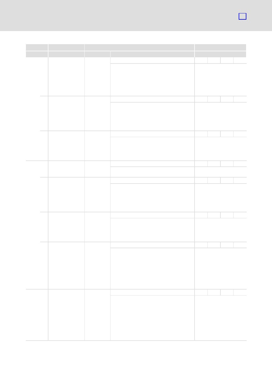
Characteristics
Possible settings
Name
Index
Description
Selection
Lenze
60F6
h
0 torque_control_
parameters
REC
UINT8
RO
Ċ
Reading−out of PI−controlled
current controller data.
The gain and the time
constant apply to both the
field−generating and the
torque−generating current
controller.
1 torque_control_
gain
256
0
{1}
32 × 256
Ċ
UINT16
RW
Ċ
Setting of the proportional
gain of the current controller.
From the SDC program:
K
p
= 1.0
Setting here:
1.0 × 256 = 256 (100
h
)
2 torque_control_
time
2000
100
{1
ms}
65500
Ċ
UINT16
RW
Ċ
Setting of the current
controller time constant.
From the SDC program:
T
n
= 2 ms
Setting here: 2 ms = 2000
ms
60F9
h
0 velocity_control_
parameter_set
REC
UINT8
RO
Ċ
Reading−out of the speed
controller data.
1 velocity_control_
gain
179
26
{1}
64 × 256
Ċ
UINT16
RW
MAP
Setting of the speed
controller gain.
From the SDC program:
K
p
= 0.7
Setting here:
0.7 × 256 = 179
2 velocity_control_
time
8000
200
{1
ms}
32000
Ċ
UINT16
RW
MAP
Setting of the speed
controller time constant.
From the SDC program:
T
n
= 8 ms
Setting here: 8 ms = 8000
ms
4 velocity_control_
filter_time
1600
200
{1
ms}
32000
Ċ
UINT16
RW
MAP
Setting of the filter time
constant for the actual speed
value.
The filter serves to reduce
the measurement noise.
From the SDC program:
T = 1.6 ms
Setting here:
1.6 ms = 1600
ms
60FA
h
0 control_effort
{speed units}
VAR
INT32
RO
MAP
Reading−out of the position
controller correction speed.
The correction speed is the
difference between the set
position and the actual
position with consideration
of the gain.
This value is internally
supplied to the speed
controller as a setpoint.