Appendix, Index table – Lenze 931K User Manual
Page 131
Appendix
Index table
l
131
KHB 13.0002−EN 4.1
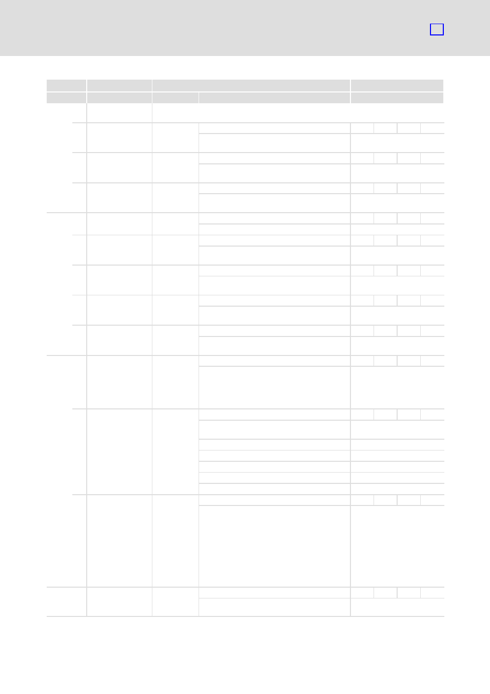
Characteristics
Possible settings
Name
Index
Description
Selection
Lenze
2015
h
Transmit PDO2
Mask
0 number_of_entries
ARR
UINT8
RO
Ċ
Maximum number of
supported subindexes
1 tpdo2_transmit_
mask_low
FFFFFFFF
h
00000000
h
{1
h
}
FFFFFFFF
h
Ċ
UINT32
RW
Ċ
Mask for masking out
individual bits of the PDOs.
2 tpdo2_transmit_
mask_high
FFFFFFFF
h
00000000
h
{1
h
}
FFFFFFFF
h
Ċ
UINT32
RW
Ċ
Mask for masking out
individual bits of the PDOs.
2090
h
0 velocity_ramps
REC
UINT8
RO
Ċ
Not used.
2 velocity_
acceleration_pos
01E84800
h
00000000
h
{1
h
}
FFFFFFFF
h
Ċ
UINT32
RW
Ċ
Setting of the positive ramp
acceleration.
3 velocity_
deceleration_pos
01E84800
h
00000000
h
{1
h
}
FFFFFFFF
h
Ċ
UINT32
RW
Ċ
Setting of the positive ramp
deceleration.
4 velocity_
acceleration_neg
01E84800
h
00000000
h
{1
h
}
FFFFFFFF
h
Ċ
UINT32
RW
Ċ
Setting of the negative ramp
acceleration.
5 velocity_
deceleration_neg
01E84800
h
00000000
h
{1
h
}
FFFFFFFF
h
Ċ
UINT32
RW
Ċ
Setting of the negative ramp
deceleration.
2415
h
0 current_limitation
REC
INT8
RO
Ċ
Limitation von I
max
(independently of the
operating mode).
Torque−limited speed
operation is possible.
1 limit_current_
input_channel
00
h
00
h
{1
h
}
04
h
Ċ
INT8
RW
Ċ
Setpoint source for the
limiting torque.
0
No limitation
1
AIN0
2
AIN2
3
RS232
4
CAN
2 limit_current
0
0
{1 mA}
100000
Ċ
INT32
RW
Ċ
l
Setpoint source RS232,
CAN: limitation of the
torque−proportional
current
l
Setpoint sources AIN0,
AIN1: Selection of the
scaling factor for the
analog inputs. The current
in mA corresponds to an
applied voltage of 10 V.
2C0A
h
0 lower_8bit_of_
60FD
VAR
INT8
RO
MAP
Low byte (digital inputs and
outputs).