2 state diagram of the drive controller, State diagram of the drive controller, Device control – Lenze 931K User Manual
Page 91: Danger
Device control
State diagram
State diagram of the drive controller
l
91
KHB 13.0002−EN 4.1
8.1.2
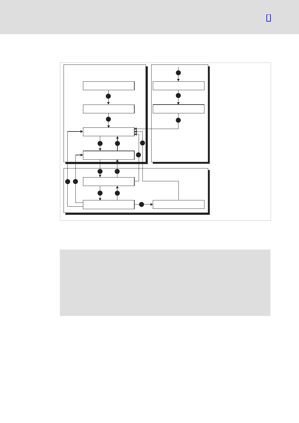
State diagram of the drive controller
Start
Switch_On_Disabled
Ready_To_Switch_On
Switched_On
Operation_Enable
Quick_Stop_Active
Fault
Fault_Reaction_Active
Not_Ready_To_Switch_On
0
15
2
3
4
5
6
7
8
9
10
11
13
14
1
1
0
2
12
931e_421
Fig. 16
State diagram of the drive controller
0 Power disabled (power stage is inhibited)
1 Fault (error)
2 Power enabled (power stage is switched on)
{
Danger!
Dangerous voltage
Power stage inhibited means that the power transistors cannot be controlled
anymore. However, a dangerous voltage may still be applied to the motor.
Possible consequences:
ƒ
This means a danger to life when working on the motor.
Protective measures:
ƒ
Disconnect the motor from the mains before starting to work on it.
After being switched on, the drive controller is initialised and finally reaches the
Switch_On_Disabled state. In this state, the CAN communication is fully operational and
the drive controller can be parameterised (e.g. the speed control operating mode can be
set). The power stage is switched off and the shaft can thus be rotated freely.
Via the state transitions 2, 3, 4 (basically corresponding to the CAN controller enable) the
Operation_Enable state is reached. In this state the power stage is switched on and the
motor is controlled according to the set operating mode. It is therefore essential to ensure
in advance that the drive is parameterised correctly and that a corresponding setpoint is
set to zero.