2 description of the objects, Description of the objects, Parameter setting – Lenze 931K User Manual
Page 79
Parameter setting
Current controller and motor adaptation
Description of the objects
l
79
KHB 13.0002−EN 4.1
7.4.2
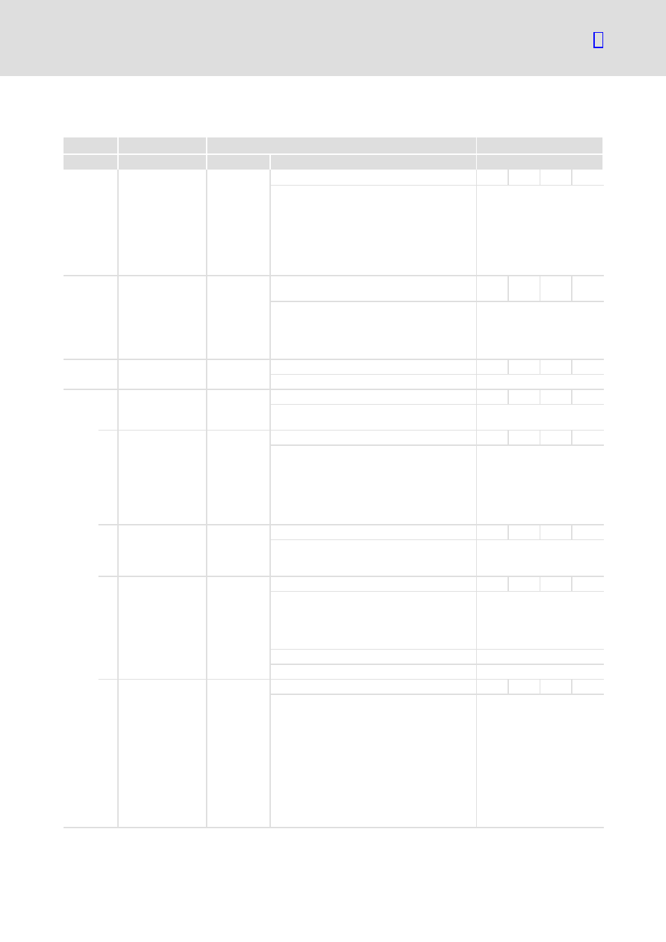
Description of the objects
Index
Name
Possible settings
Characteristics
Lenze
Selection
Description
6075
h
0 motor_rated_
current
500
0
{1 mA}
VAR
UINT32
RW
MAP
Input value for I
r
(specified on
the motor nameplate). The
value must be smaller than
the rated controller current.
If this index is changed, the
index 6073
h
max_current
also must be parameterised
again.
6073
h
0 max_current
2023
0
{motor_rated_
current/1000}
65535
VAR
INT16
RW
MAP
Input value for I
max
.
The value for index 6075
h
motor_rated_ current must
be entered before this value
can be input.
604D
h
0 pole_number
2
2
{2}
254
VAR
UINT8
RW
MAP
Number of motor poles.
6410
h
0 motor_data
REC
UINT8
RO
Ċ
Reading−out of the motor
data.
3 iit_time_motor
2000
0
{1 ms}
10000
Ċ
UINT16
RW
Ċ
Setting of the time interval
for which the motor can be
fed with I
max
(index 6073
h
).
When this time has expired,
the motor is automatically
limited to the value set under
6075
h
.
4 iit_ratio_motor
{1 }
Ċ
UINT16
RO
MAP
Reading−out of the actual
utilisation ratio of the I
2
t
limitation.
10 phase_order
1
0
{1}
1
Ċ
UINT16
RW
MAP
Setting of the phase
sequence.
See ’angle encoder’ dialog
box in the SDC
parameterisation program.
0
Phase sequence: left
1
Phase sequence: right
11 resolver_offset_
angle
11360
−32767
{1 inc}
32767
Ċ
INT16
RW
MAP
Setting of the angle encoder
orientation with respect to
the permanent magnetic
field of the rotor.
See ’angle encoder offset
angle’ dialog box in the SDC
parameterisation program.
Conversion:
a = offset angle
× 32767/180°
= 11360 (with offset angle
= 62.4°)