4 connection of can bus master, Connection of can bus master, Electrical installation – Lenze 931K User Manual
Page 15
Electrical installation
Connection of CAN bus master
l
15
KHB 13.0002−EN 4.1
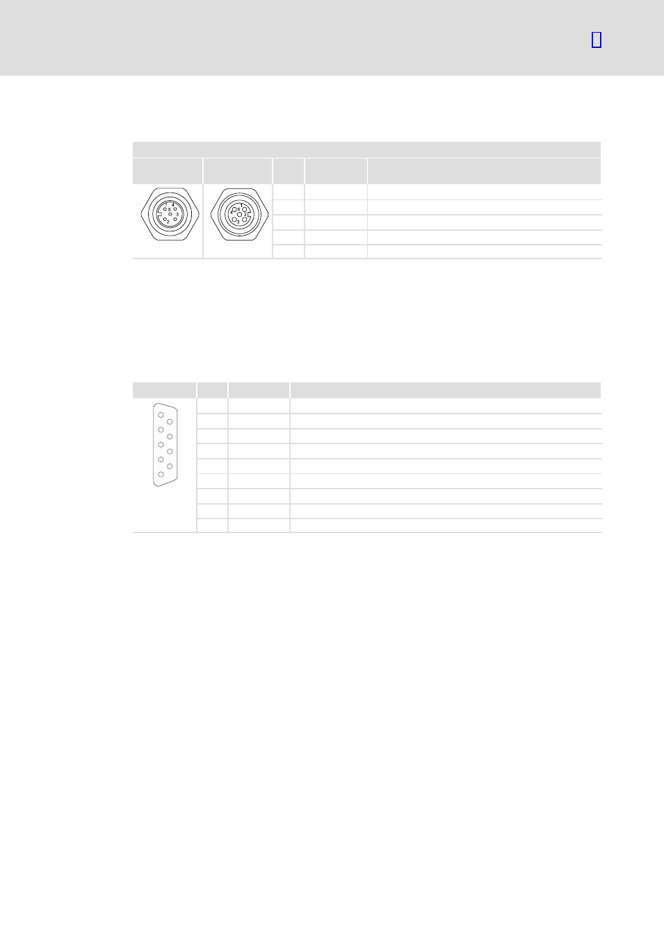
Connection plan for M12 socket (931K)
X4.1 / X4.2
Input contact
pattern
Output contact
pattern
Pin
Signal
Explanation
1
CAN_SHLD
CAN_Shield
2
Ċ
Reserved
3
CAN_GND
CAN_Ground
4
CAN_H
CAN_HIGH (high is dominant)
5
CAN_L
CAN_LOW (low is dominant)
4.4
Connection of CAN bus master
The below table shows the assignment of a 9−pin Sub−D socket such as provided by most
CAN masters for the connection of field devices.
Connection of the CAN bus to a 9−pin Sub−D socket
View
Pin
Signal
Explanation
1
6
2
7
3
8
4
9
5
1
Ċ
Reserved
2
CAN−LOW
CAN−LOW (low is dominant)
3
CAN−GND
CAN ground
4
Ċ
Reserved
5
(CAN−SHLD)
Optional CAN shield
6
(GND)
Optional ground
7
CAN−HIGH
CAN−HIGH (high is dominant)
8
Ċ
Reserved
9
(CAN−V+)
Optional external CAN voltage supply
Tab. 1
CAN Sub−D socket