2 electrical connections of canopen, Electrical connections of canopen, Electrical installation – Lenze 931K User Manual
Page 13: Up to 128 bus nodes possible
Electrical installation
Electrical connections of CANopen
l
13
KHB 13.0002−EN 4.1
4.2
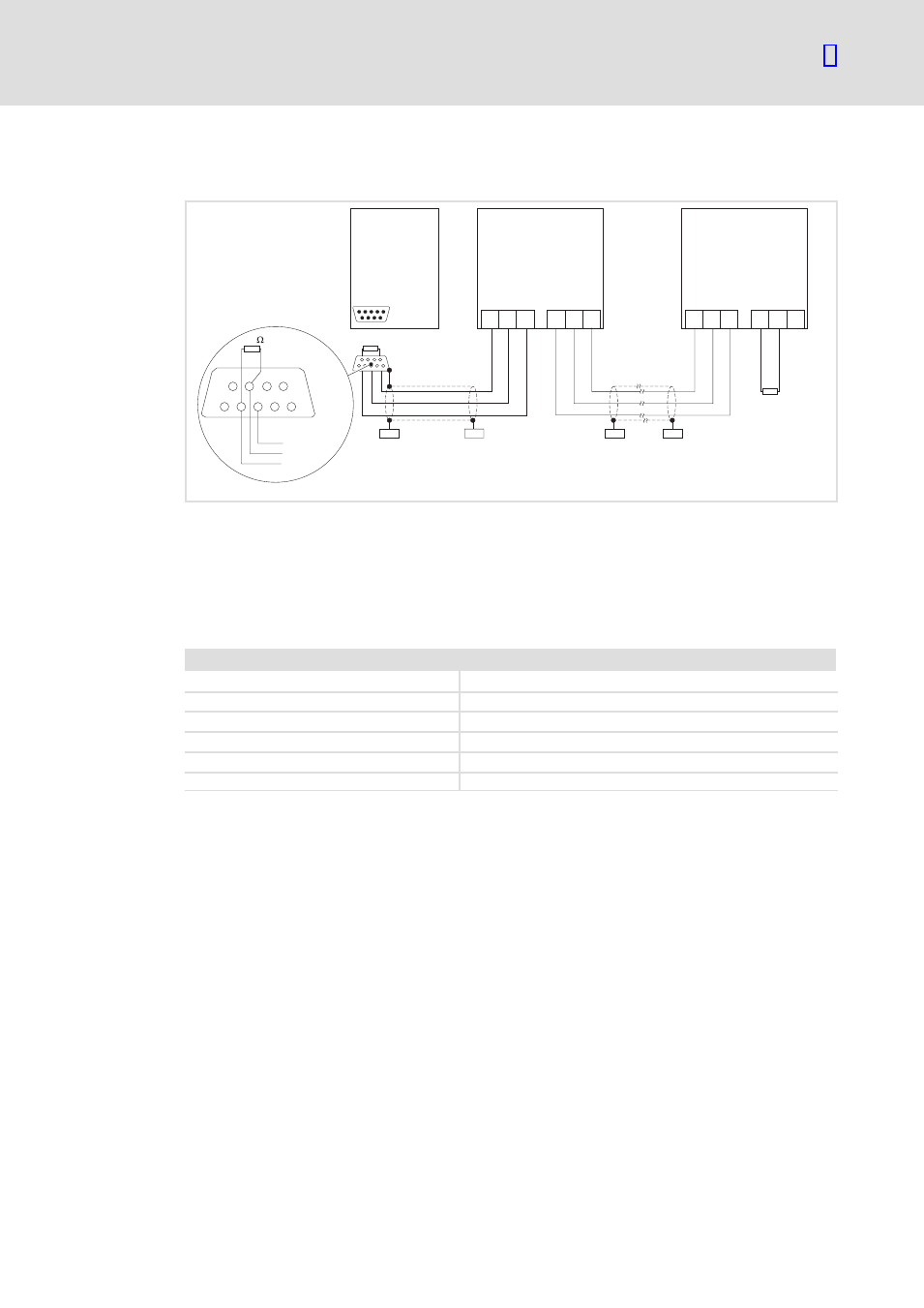
Electrical connections of CANopen
LO
LO
LO
LO
CG
CG
CG
CG
HI
HI
HI
HI
X4.1
X4.1
X4.2
X4.2
A
2
A
1
A
n
PES
PES
PES
PES
CAN-GND
CAN-LOW
CAN-HIGH
120
1 2
3 4 5
6 7 8 9
120
W
120
W
931e_420
Fig. 1
Basic wiring of CANopen with Sub−D connector to the master
A
1
Node 1 − master (e.g. PLC)
A
2
Node 2 − slave (e.g. drive controller 931E)
A
n
Node n − slave, n = max. 127
Specification of the transmission cable
Please observe our recommendations for signal cables.
Bus cable specification
Cable resistance
135 − 165
W/km, (f = 3 − 20 MHz)
Capacitance per unit length
£ 30 nF/km
Loop resistance
< 110
W/km
Wire diameter
> 0.64 mm
Wire cross−section
> 0.34 mm
2
Wires
double twisted, insulated and shielded
ƒ
Connection of the bus terminating resistors:
– One resistor of 120
W each at the first and last bus node
ƒ
Communication protocol
– CANopen (CAL−based communication profile DS 301/DSP 402)
ƒ
Bus extension:
– 40 m for max. data transfer rate of 1 Mbps
– Up to 1 km for reduced data transfer speed
ƒ
Signal level according to ISO 11898
ƒ
Up to 128 bus nodes possible