Safety engineering – Lenze E94AYAE SM301 User Manual
Page 93
Safety engineering
Safe bus interfaces
PROFIsafe connection
l
93
EDS94AYAE EN 7.0
Control byte
For the PROFIsafe V1 mode only the indicated bits of the PROFIsafe control byte are
supported:
Assignment
Bit
Byte
7
6
5
4
3
2
1
0
4
−
−
−
activate_FV
−
−
−
−
Tab. 1−8
Structure of the PROFIsafe control byte in V1 mode
Bit coding − control byte
Bit
Name
Value
Description
4
activate_FV
1
The PROFIsafe output data is passivated.
−
0
Reserved for future extensions
Tab. 1−9
Detailed specification of the control byte in V1 mode
For the PROFIsafe V2 mode only the indicated bits of the PROFIsafe control byte are
supported:
Assignment
Bit
Byte
7
6
5
4
3
2
1
0
4
−
−
Toggle_h
activate_FV
−
R_cons_nr
−
−
Tab. 1−10
Structure of the PROFIsafe control byte in V2 mode
Bit coding − control byte
Bit
Name
Value
Description
2
R_cons_nr
1
Reset of the consecutive number.
4
activate_FV
1
The PROFIsafe output data is passivated.
5
Toggle_h
1/0
Change increases the consecutive number.
−
0
Reserved for future extensions
Tab. 1−11
Detailed specification of the control byte in V2 mode
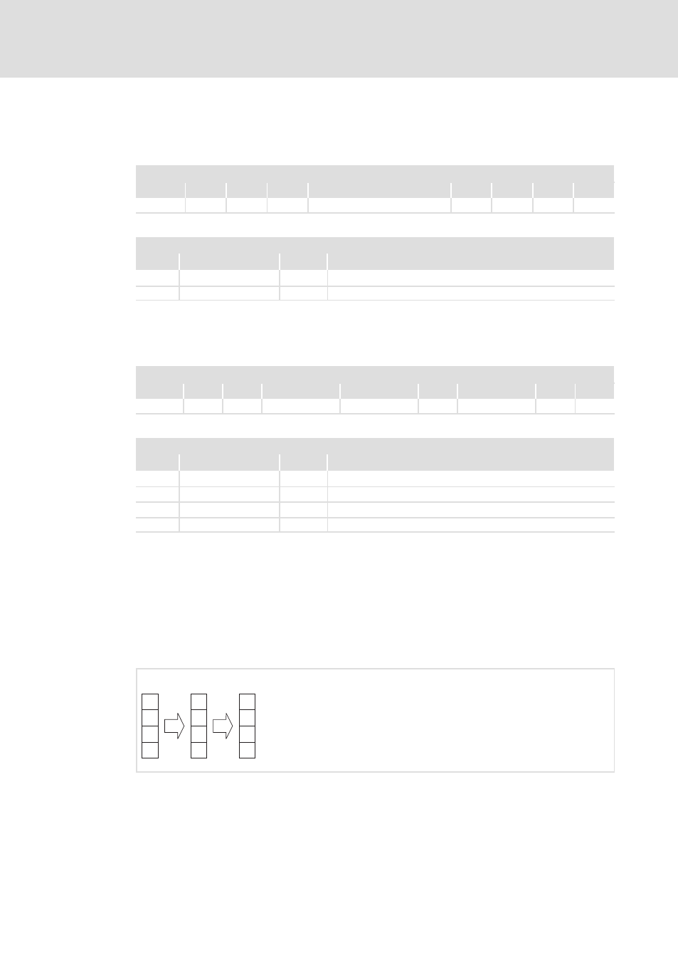
Control data filter
Unused functions in the control data of the safety bus must be set to "Inhibit" via the
parameter "S−bus: Control data filter" (C15113). After this, the functions can no longer be
activated via the safety bus independently of the transferred control data. As of
SM301 V1.2, the filtered control data is indicated in "S−bus: Display of control data"
(C15115).
1
0
1
0
a
a
i
i
1
0
1
1
0
1
2
SSP94SM301
Fig. 1−12
Function example − filter
0 Control data, incoming (0 = active, 1 = inactive)
1 Control data filter
(Selection in the »Engineer«: a = "pass through", i = "inhibit")
2 Effective control data (0 = active, 1 = inactive)