Brother HL-1260 User Manual
Page 55
IV
- 7
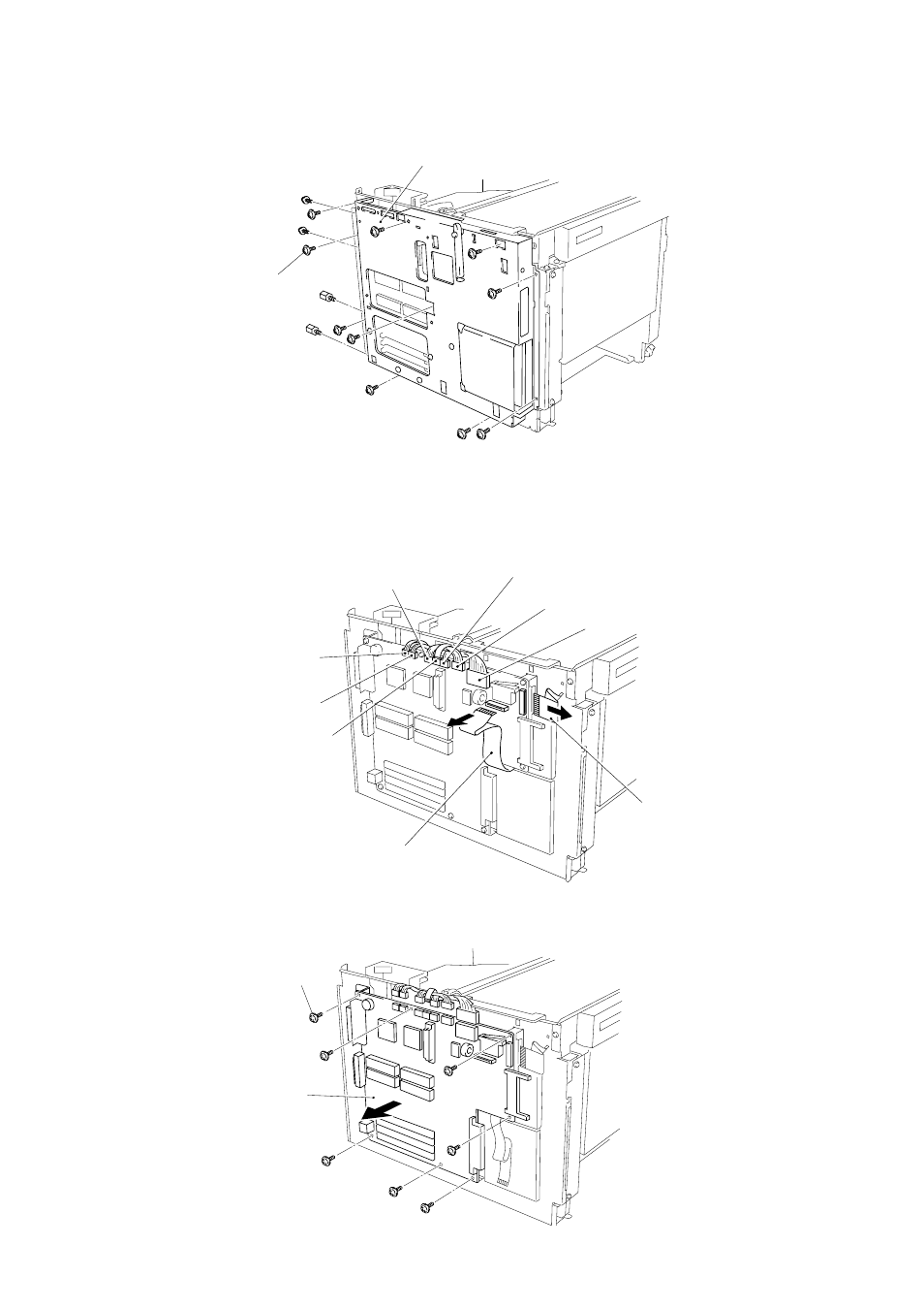
(3) Remove the PCB holder by loosening PCB holder fixing screws, 2 centronics connector
screws and 2 RS-232C connector screws.
Figure 4.12
(4) Remove the switch flat cable 21P and the feed flat cable 20P.
(5) Remove the fan harness 3P, the fuser harness 4P, the SCN harness 4P, the SCN flat cable 6P,
the DC motor harness 4P, the HV harness 16P and the LV harness 8P.
Figure 4.14
Figure 4.13
PCB holder
Screws
SCN harness 4P
HV harness 16P
LV harness 8P
Switch flat cable 21P
Feed flat cable 20P
SCN flat cable 6P
Fuser harness 4P
7 screws
Main PCB assy
(6) Remove the main PCB assy.
Fan harness 3P
DC motor harness 4P
See also other documents in the category Brother Printers:
- HL-2240 (522 pages)
- HL-2240 (21 pages)
- HL-2240 (2 pages)
- HL-2240 (150 pages)
- HL 5370DW (172 pages)
- HL-2170W (138 pages)
- HL 5370DW (203 pages)
- HL 2270DW (35 pages)
- HL 2270DW (47 pages)
- HL 5370DW (55 pages)
- HL-2170W (52 pages)
- HL-2170W (137 pages)
- PT-1290 (1 page)
- DCP-385C (2 pages)
- DCP-383C (7 pages)
- DCP-385C (122 pages)
- MFC 6890CDW (256 pages)
- DCP-585CW (132 pages)
- Pocket Jet6 PJ-622 (48 pages)
- Pocket Jet6 PJ-622 (32 pages)
- Pocket Jet6 PJ-622 (11 pages)
- Pocket Jet6Plus PJ-623 (76 pages)
- PT-2700 (90 pages)
- PT-2700 (180 pages)
- PT-2100 (58 pages)
- PT-2700 (34 pages)
- PT-2700 (62 pages)
- DCP-8110DN (22 pages)
- HL 5450DN (168 pages)
- HL 5450DN (2 pages)
- HL 5450DN (2 pages)
- HL 5470DW (30 pages)
- MFC-J835DW (13 pages)
- DCP-8110DN (36 pages)
- HL 5470DW (177 pages)
- HL 5450DN (120 pages)
- DCP-8110DN (13 pages)
- HL 5470DW (34 pages)
- HL-S7000DN (9 pages)
- HL-6050D (179 pages)
- HL-6050D (37 pages)
- HL-7050N (17 pages)
- HL-6050DN (138 pages)
- PT-1280 (1 page)
- PT-9800PCN (104 pages)