Chapter ii theory of operation, Basic operations – Brother HL-1260 User Manual
Page 17
II -
1
CHAPTER
II
THEORY OF OPERATION
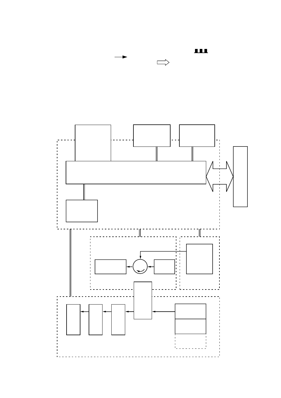
This chapter describes the printer functions, the relationship between the electrical systems and
mechanical systems, and the timing of operations. Striped conduits ( ) indicate mechanical
linkages; solid thin arrows ( ) appearing with a signal name indicate the transmission of
single control signals and outlined thick arrows ( ) indicate the transmission of groups of
signals.
1.
BASIC OPERATIONS
1.1 Mechanical Configuration
The printer functions can be divided into four blocks: the laser/scanner system, the image
formation system, the paper pick-up/feed system and the control system.
Figure 2.1
Expansion memory
(SIMM)
Font cartridge/card
Optional I/O
(MIO)
External Device
Control panel
IMAGE FORMATION SYSTEM
Cleaning unit
Photosensitive drum
Developing
unit
Laser/scanner
unit
LASER/SCANNER
SYSTEM
Transfer
separation
unit
Delivery rollers
Fixing unit
Feeder
Tray 1
Tray 2
(Option)
MP tray
Main PCB
CONTROL SYSTEM
PAPER PICK-UP/FEED SYSTEM
- HL-2240 (522 pages)
- HL-2240 (21 pages)
- HL-2240 (150 pages)
- HL-2240 (2 pages)
- HL 5370DW (172 pages)
- HL-2170W (138 pages)
- HL 5370DW (203 pages)
- HL 2270DW (35 pages)
- HL 2270DW (47 pages)
- HL 5370DW (55 pages)
- HL-2170W (52 pages)
- HL-2170W (137 pages)
- PT-1290 (1 page)
- DCP-385C (122 pages)
- MFC 6890CDW (256 pages)
- DCP-585CW (132 pages)
- DCP-385C (2 pages)
- DCP-383C (7 pages)
- Pocket Jet6 PJ-622 (32 pages)
- Pocket Jet6 PJ-622 (11 pages)
- Pocket Jet6 PJ-622 (48 pages)
- Pocket Jet6Plus PJ-623 (76 pages)
- PT-2700 (34 pages)
- PT-2700 (62 pages)
- PT-2700 (90 pages)
- PT-2700 (180 pages)
- PT-2100 (58 pages)
- HL 5450DN (2 pages)
- DCP-8110DN (22 pages)
- HL 5450DN (168 pages)
- HL 5450DN (2 pages)
- HL 5470DW (177 pages)
- HL 5450DN (120 pages)
- DCP-8110DN (13 pages)
- HL 5470DW (34 pages)
- HL-S7000DN (9 pages)
- HL 5470DW (30 pages)
- MFC-J835DW (13 pages)
- DCP-8110DN (36 pages)
- HL-6050D (37 pages)
- HL-7050N (17 pages)
- HL-6050DN (138 pages)
- HL-6050D (179 pages)
- PT-1280 (1 page)
- PT-9800PCN (32 pages)