Residue pump, Check valve in the residue circuit, Overflow sensor on residue vessel – Heidolph Automatic Module Distimatic User Manual
Page 25
Installation
Installation
48
49
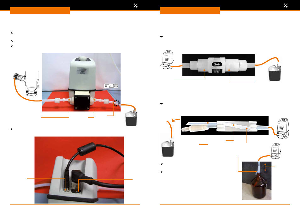
Residue pump
(only on Distimatic including automatic drainage of residue)
Connect PTFE tubes Ø 8 mm to connections (23) and (26) and tighten until hand-
tight.
Set the rotary knob (24) to the maximum flow rate (100% = MAX).
To integrate the check valve, vertically cut through the PTFE tube with the HOLEX
hose cutter at about point (25) shown in the circle.
Connect power cord into connection (27) and control cable into connection (28) and
tighten until hand-tight.
Residue
Residue
23
27
28
26
25
Connect PTFE tubes Ø 8 mm to connections (29) and (30) and tighten until hand-
tight.
Important: Observe flow direction!
Check valve in the residue circuit
(only on Distimatic including automatic drainage of residue)
Cut off the end (31) of the PTFE tube Ø 6 mm with a cutting knife only at an angle of
approx. 45° and route through the connections (33) and (32) of the overflow sensor.
Overflow sensor on residue vessel
29
30
33
32
31
Attach overflow sensor safely on the edge
(34) of the residue vessel.
The immersion depth of the PTFE tubes in
the vessel may be determined by pulling or
pushing the PTFE tube (35).
34
36
Residue