Final installation, N o t e – ETC Unison ERn Rack-mount Control Enclosure User Manual
Page 35
5
Final Installation and Power Up
31
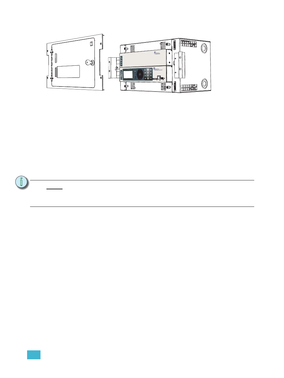
Final Installation
Step 1:
Install the Paradigm architectural control processor (P-ACP) in the appropriate
module slot.
Step 2:
Install the Paradigm station power module (P-SPM) in the module slot above the
Paradigm architectural control processor.
Step 3:
Install option modules if they are not installed. For an ERn4, you may install a
Paradigm dual repeater module (P-DREP), two blank modules, or a Paradigm
station repeater module (P-REP) in the top module slot of the enclosure with a
blank module below.
Step 4:
Install either the ERn blank option module or the redundant power supply (ERn-
RPS) in the lower option module slot.
a: If installing the redundant rack power supply (ERn-RPS) module in the option
module slot, be certain you have completed the installation requirements.
See “Install Rack Options” on page 21.
Step 5:
Install blank air flow (ERn-BM) modules in any unused module slot in the
enclosure to maintain the required convection cooling requirements.
Step 6:
For 230 VAC CE ERn enclosures, reinstall the module retention bar to the left
side of the ERn enclosure. This module retention bar is required to maintain CE
compliance.
N o t e :
The optional redundant power supply (ERn-RPS) is not supported in ERn4
enclosures at 230 VAC. Instead the ERn4 at 230 VAC is shipped from the factory
with a rack power supply installed in the top (normal) position and in the lower
option module slot as standard.