Terminate linkpower (lon®) control wiring, Terminate linkpower (lon, Control wiring – ETC Unison ERn Rack-mount Control Enclosure User Manual
Page 20: N o t e
16
Unison
®
ERn Rack Mount Enclosure Installation Manual
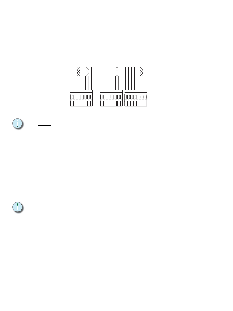
DMX Input/Output Termination: Insulation Displacement Connectors
The graphic below illustrates DMX termination layout for an insulation displacement
connector (IDC). This connector type is intended for use with Belden 1583A (or approved
equal, such as Category 5, 5E, or 6) cable type.
The insulation displacement connector kit (IDC) may be requested from the factory but is
not supplied as standard. Request the IDC Pluggable Connector Termination kit, part
number 4100A1013. Be aware that cable other than Belden 1583A may have different color
code for its wire pairs.
Terminate LinkPower (LON
®
) Control Wiring
Unison control stations communicate with the Paradigm architectural control processor
using the Echelon
®
LinkPower network. Termination is available for up to six home runs of
LinkPower (LON) data runs utilizing Belden 8471 cable (or its equivalent) plus one 14 AWG
(2.5mm
2
) ESD drain wire when the data cable is not installed in grounded metal conduit.
LinkPower wiring is topology-free and polarity independent utilizing a LonWorks network.
Wiring may be bus, star, loop, home run, or any combination of these. The total combined
length of LinkPower data runs cannot exceed 1,640 feet (500m), with a maximum distance
of 1,313 feet (400m) between any two (un-repeated) communicating devices. Without a
repeater, no device may be more than 1,313 feet (400m) away from the Paradigm ACP.
Standard LON interoperability requires that there should be a maximum of only one
repeater between any two LON devices. This means that only one repeater module,
whether a Paradigm repeater module (P-REP) or a Paradigm dual repeater module
(P-DREP), may be used per Paradigm ACP. Each individual topology-free network can
have no more than 62 LON stations with a repeater option and Paradigm ACP.
Step 1:
Pull Belden 8471 (or approved equal type) control wiring to the rear panel of the
ERn enclosure.
Step 2:
Strip 3/16” (5mm) of insulation from the ends of each wire pair.
N o t e :
All low voltage control cables must run in separate conduit from power wires.
N o t e :
When utilizing a Paradigm station repeater module (P-REP) or Paradigm dual
station repeater module (P-DREP), terminate the repeated LON segment(s) and
auxiliary power wiring to the related rear panel I/O board.
1
2
3
4
5
6
7
8
n/c
n/c
COM
Data +
Data -
O
RG
W/ORG
W/BRN
COM
Data +
Data -
O
RG
W/ORG
W/BRN
Use this DMX Pass-Thru
connector when
daisy-chaining to
another rack or
DMX device...
DMX A
Thru
DMX B
Thru
1
2
3
4
5
6
7
8
1
2
3
4
5
6
7
8
COM
Data +
Data +
Data -
Data -
O
RG
W/ORG
BRN
GRN
W/GRN
BLU
W/BLU
W/BRN
ORG
W/ORG
BRN
GRN
W/GRN
BLU
W/BLU
W/BRN
COM
From source
DMX A
From source
DMX B