Simpliq – ElmoMC SimplIQ Software Manual User Manual
Page 137
SimplIQ
Software Manual
Unit Modes
MAN-SIMSW (Ver. 1.4)
10-7
Parameters Description
switches (RLS or FLS)
Table
10-4: Stop Manager Parameters
Reference generator
output (software +
auxiliary)
SD
Acceleration/Deceleration
Lim iter
LV[2],HV[2] speed lim iter
Com m and to
Speed Controller
-
Stop condition
(Stop, RLS, FLS)
0
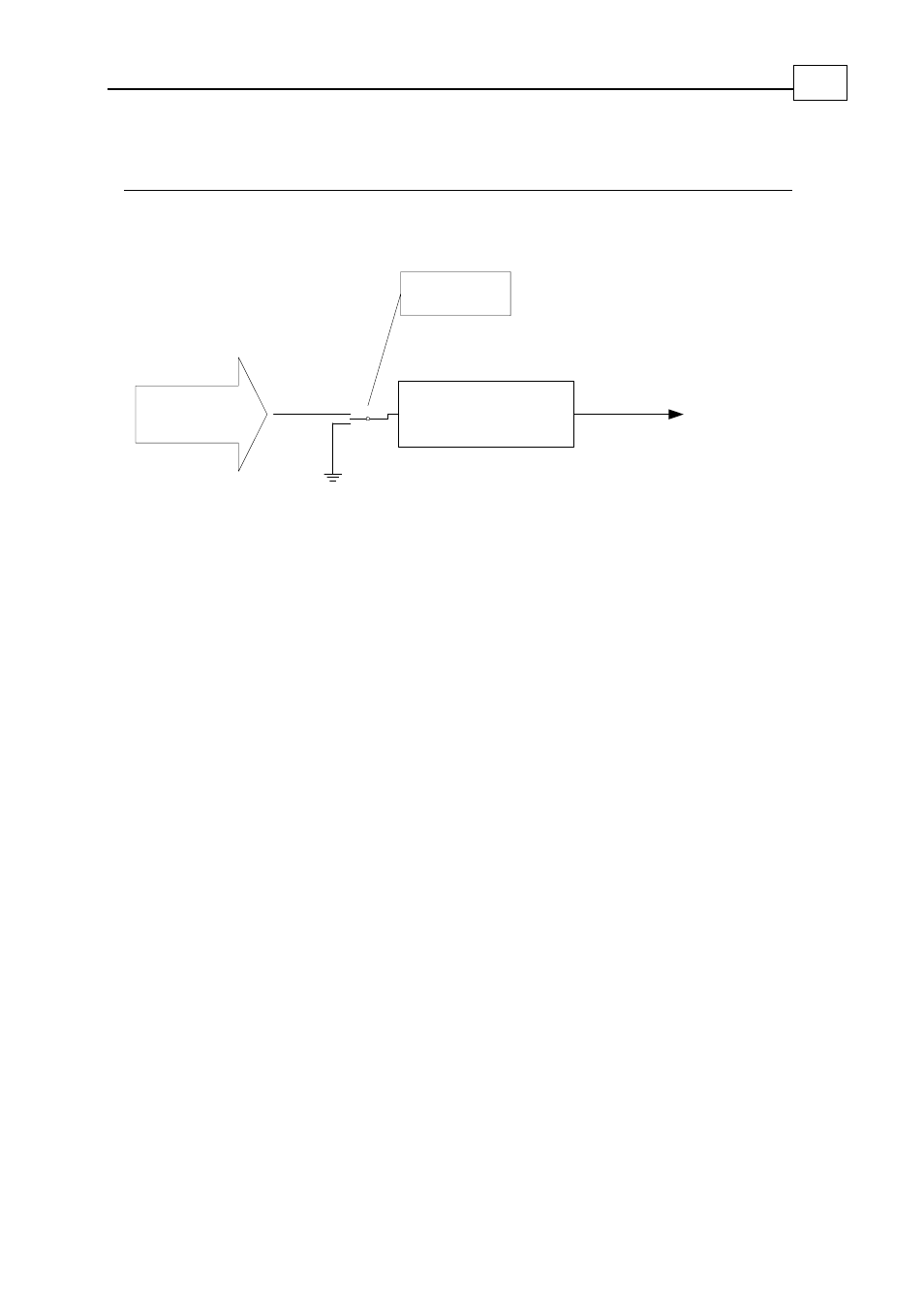
Figure
10-6: Speed Mode Stop Manager
The stop manager prevents the speed controller command from changing abruptly by
limiting the rate of reference change to SD counts/second
2
. When the stop manager stops
the motor due to a switch action, the reference generator is replaced by a zero command
at the input to the stop manager. The stop manager uses the SD parameter to decelerate
the motor command from the output of the reference generator to a complete stop.
When the switch action terminates (a Stop switch is released, for example), the stop
manager uses the SD acceleration to recover the speed command to the output of the
reference generator. Stop manager operation includes the following factors:
The stop manager must limit the speed command to the range [VL[2]…VH[2]].
Although both the software speed command and the external speed command are
each limited to the legal range, their total value may be out of range.
When the stop manager stops the command to the speed controller, it does not affect
the reference generator, which continues to behave normally. When the switch action
is complete, the stop manager attempts to recover the speed controller command to
the output to the reference generator.
The stop manager limits the decelerations and accelerations due to abrupt changes of
the auxiliary reference. The SD parameter is the only acceleration limiter for the
auxiliary input. The AC and DC parameters are only relevant to software commands.
When AC and DC are greater than SD, they become irrelevant, because SD further
limits acceleration.
The IL[N] command can program a variety of stop options to an input pin. A pulse at
the pin can be directed to the stop manager (as in the following example), stop the
software reference generator, or both.
Example:
SD=100,000, MO=1, AC=10,000, DC=10,000, JV=5000, BG;
At the time of 0.2 seconds, a switch programmed as hard stop is activated, and released
at the time of 0.4 seconds. The following waveforms result: