2 the pi current controller, 2 the pi current controller -5, Simpliq – ElmoMC SimplIQ Software Manual User Manual
Page 128
SimplIQ
Software Manual
The Current Controller
MAN-SIMSW (Ver. 1.4)
9-5
9.2
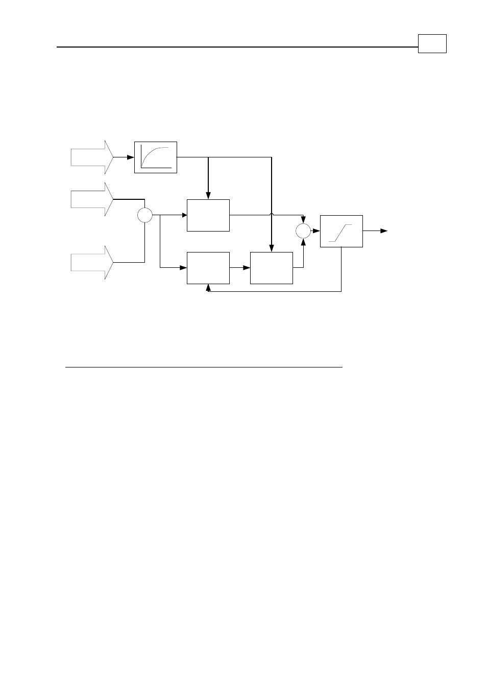
The PI Current Controller
The controllers for the IQ and ID components are similar, as depicted in the following
block diagram:
Kp[1]/VB
KI[1]/VB
-
Σ
Feedback
Com m and
∑
ε
k
k
ε
Integrator
Proportional gain
Integral gain
Saturation
Σ
Anti wind up
O utput
Bus voltage
VB
Bus Voltage Filter
Figure
9-4: Current PI Controller
The following table lists the roles of the inputs and outputs in the IQ and ID controllers:
Parameter
Q Controller
D Controller
Bus voltage
Measured and filtered motor power DC voltage
Command Torque
command 0
Feedback IQ
ID
Output VQ
VD
Table
9-1: IQ and ID Controller Parameters
Saturation is given by:
0.5 TS/25 * 10
-3
where:
TS is the current controller sampling time, in microseconds.
25 * 10
-3
is the period of the 40-MHz PWM generator clock, in microseconds.
The proportional and integral gains are divided by the DC voltage because the output of
the current controller is the PWM duty cycle.
The PWM duty cycle sets the corresponding motor terminal voltage to:
Motor terminal voltage = (PWM duty cycle) x (DC power voltage).
This equation shows that the uncertainty in the DC power voltage acts as a gain
uncertainty for the current controller.