Simpliq, Mc cl pl ] 1 [ 1 log ] 2, 1 [ ] 1 [ 1 log pl cl – ElmoMC SimplIQ Software Manual User Manual
Page 127
SimplIQ
Software Manual
The Current Controller
MAN-SIMSW (Ver. 1.4)
9-4
Slower time constants in the low-pass filter permit a peak current demand for longer
times, but also take more time to recover from a limitation to CL[1]. The time constant τ
of the low-pass filter is selected by PL[2] as follows:
⎥⎦
⎤
⎢⎣
⎡ −
−
=
MC
CL
PL
]
1
[
1
log
]
2
[
τ
With this selection, when PL[2] is set to MC, and after the current demand has been zero
for a long time, the drive will permit a maximum of PL[2] seconds of peak current, and
then switch to continuous current limiting.
For other settings of PL[1], the maximum time for which the peak current can be
maintained, after the current demand has been zero for a long time is:
-
τ
⋅
⎥
⎦
⎤
⎢
⎣
⎡
−
]
1
[
]
1
[
1
log
PL
CL
seconds
The programming range for PL[2] is very limited. In most applications, it is
recommended that PL[2] be left at its factory default of 3 seconds.
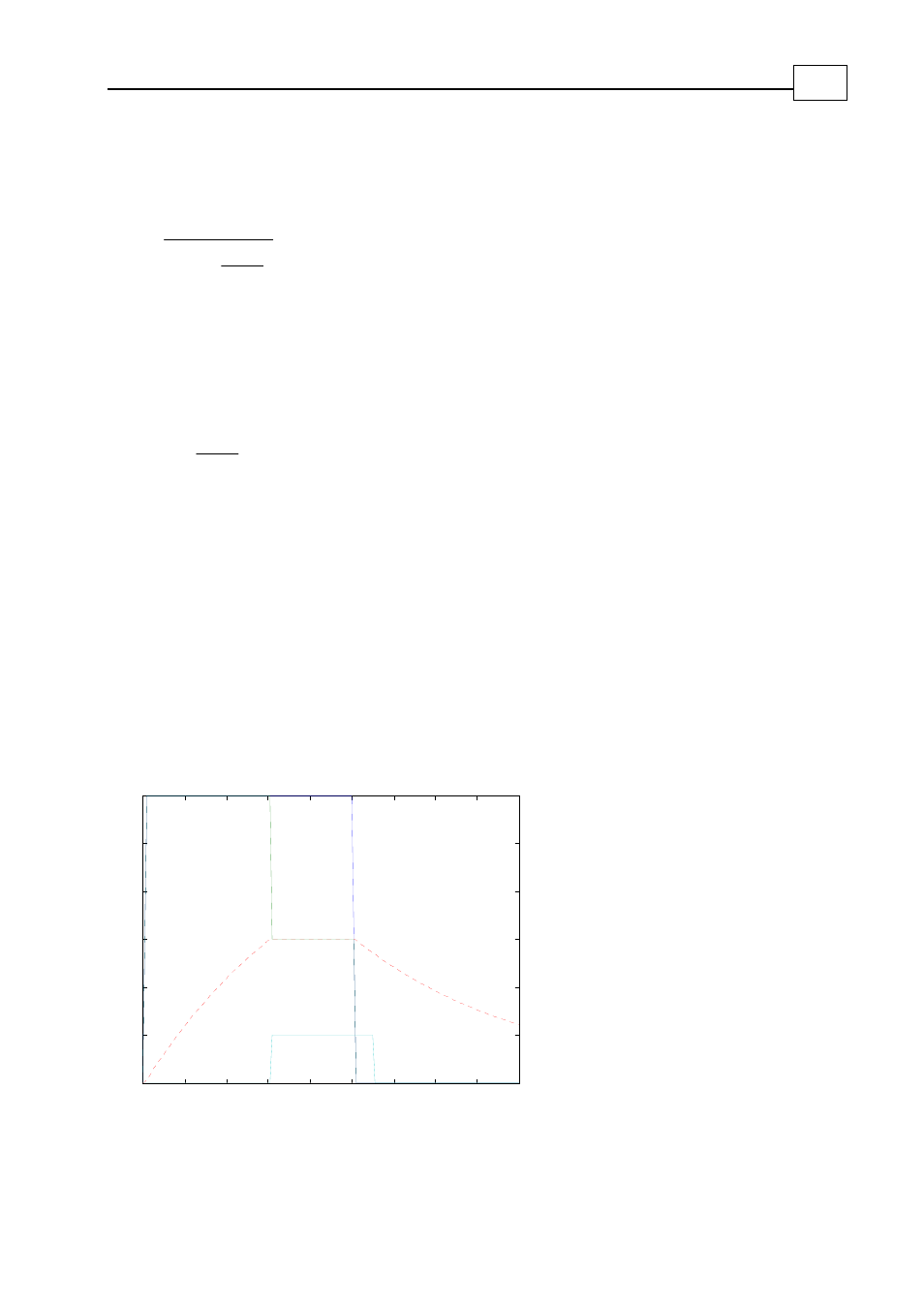
Example:
The following graph illustrates the signals related to the current command limiting
process for MC=6, PL[1]=6, PL[2] = 3 and CL[1] =3.
The motor current demand increases from zero to 6 amperes at the time of 0, and is then
decreased to 0 at the time of 5 seconds. The state of the low-pass filter increases until it
reaches the continuous current limit of 3 at the time of 3 seconds. Then, the LC flag is
raised and the motor current command is decreased to CL[1] = 3 amperes. After the
motor current command is set to zero, the state of the filter begins to drop. When it
reaches 2.7 amperes = 90% of 3 amperes, the LC flag is reset and the torque command
limit once again becomes 6 amperes.
0
1
2
3
4
5
6
7
8
9
0
1
2
3
4
5
6
A p p lica tio n curre nt d e m a nd
m o to r curre nt
co m m a nd
F ilte r sta te
L C curre nt lim it
Ind ica tio n
Figure
9-3: Current Command Limiting Example