Appendix m, Wiring – Det-Tronics UD10 DCU Emulator FlexVu Universal Display Unit User Manual
Page 63
4.2
95-8656
M-1
AppenDix m
UD10-DCU with mODEL 505 TRaNSmITTER / CgS SENSOR
noTe
For complete information regarding the Model 505 Transmitter, refer to instruction manual 95-8472.
WirinG
4000
3500
3000
2500
2000
1500
1000
500
0
18
19
20
21
22
23
24
25
26
27
28
29
30
Power Supply Voltage
Dist
ance in f
t.
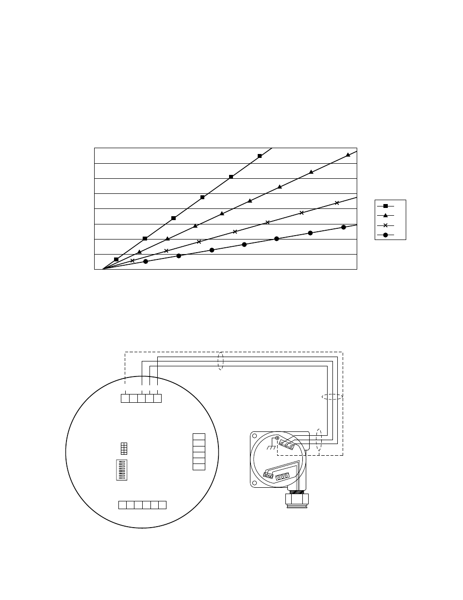
UD10-DCU with PIRECL/OPECL/NTMOS/CGS
12
14
16
18
AWG
Wire Size
Notes: Maximum cable length from power source to UD10 is 2000 feet.
Maximum cable length from UD10 to CGS sensor is 500 feet
(using 16 AWG cable minimum).
UD10
DISPLAY UNIT
MODEL 505 TRANSMITTER
CGS
SENSOR
A2519
–
SIG
RED
SENSOR
WHT
BLK
+
NOTE UD10 HOUSING MUST BE ELECTRICALLY
CONNECTED TO EARTH GROUND.
Sensor Connector
Power Supply Connector
LON Connect
or
J4
J3
J7
24 VDC
–
24 VDC
+
SHIELD
24 VDC
–
24 VDC
+
SHIELD
SHIELD
C
ALIBR
A
TE
24 VDC
–
4-20 mA
24 VDC
+
J4-1
J4-2
J4-3
J4-4
J4-5
J7
-6
J7
-5
J7
-4
J7
-3
J7
-2
J7
-1
SHIELD
2 B COM
2 A COM
SHIELD
1 B COM
1 A COM
J3-1
J3-2
J3-3
J3-4
J3-5
J3-6
SW3
J2
ON
UD10-DCU Wired to Model 505 Transmitter/CGS Sensor
- GP16XX Standard Gas Panel (20 pages)
- EQP Fire and Gas Detection/Releasing System (157 pages)
- STB Series Sensor Termination Box and Separation Kit (4 pages)
- NTMOS IP66/IP67 H2S Gas Detector (19 pages)
- UD20 FlexVu Explosion-Proof Universal Display Unit (15 pages)
- UD10 FlexVu Explosion-Proof Universal Display Unit (77 pages)
- UD10 FlexVu Universal Display SAFETY MANUAL (6 pages)
- PIRECL Infrared Carbon Dioxide Gas Detector PointWatch Eclipse (54 pages)
- FlexSonic Acoustic Detector (37 pages)
- FlexSonic Acoustic Detector SAFETY MANUAL (6 pages)
- GT3000 Series Electrochemical Gas Detector (26 pages)
- GT3000 Series Electrochemical Gas Detector SAFETY MANUAL (6 pages)
- PIRECL Infrared Hydrocarbon Gas Detector PointWatch Eclipse (69 pages)
- PIRECL Infrared Hydrocarbon Gas Detector PointWatch Eclipse SAFETY MANUAL (8 pages)
- PIR9400 PointWatch Infrared Hydrocarbon Gas Detector (34 pages)
- 505 Combustible Gas Detector Transmitter with Combustible Gas Sensor CGS (27 pages)
- PIRVOLLT Volumetric Infrared Hydrocarbon Gas Process Monitor for Light Hydrocarbons (18 pages)
- PIRVOLHV Volumetric Infrared Hydrocarbon Gas Process Monitor for Heavy Hydrocarbons (18 pages)
- PIRVOLVR Volumetric Infrared Hydrocarbon Gas Process Monitor for Vapor Recovery Systems (18 pages)
- X9800 IR Flame Detector (31 pages)
- X9800 IR Flame Detector with Pulse Output (32 pages)
- X2200 UV SIL 2 Certified Flame Detectors SAFETY MANUAL (6 pages)
- X5200 UVIR Flame Detector (35 pages)
- X5200 UVIR Flame Detector with Pulse Output (36 pages)
- X5200 UVIR Flame Detector with HART (21 pages)
- X3302 Multispectrum IR Flame Detector (37 pages)
- X3302 Multispectrum IR Flame Detector with Pulse Output (36 pages)
- X3302 Multispectrum IR Flame Detector with HART (21 pages)
- X3302 Multispectrum IR Flame Detector SAFETY MANUAL (8 pages)
- X3301 Multispectrum IR Flame Detector (40 pages)
- X3301 Multispectrum IR Flame Detector with Pulse Output (39 pages)
- X3301 Multispectrum IR Flame Detector with HART (21 pages)
- X3301 Multispectrum IR Flame Detector with Automotive (2 pages)
- X2200 UV Flame Detector (32 pages)
- X2200 UV Flame Detector with Pulse Output (33 pages)
- X2200 UV Flame Detector with HART (21 pages)
- OPECL Infrared Hydrocarbon Gas Detector (49 pages)
- OPECL Infrared Hydrocarbon Gas Detector SAFETY MANUAL (6 pages)
- U9500 Infiniti Gas Transmitter (50 pages)
- U5006 Air Duct Smoke Detector (8 pages)
- U5005 Smoke Detector (4 pages)
- EQ3750ASH EQP Addressable Smoke & Heat (ASH) Module (8 pages)
- PM-5MPX Dual Spectrum IR (17 pages)
- EQP Fire and Gas Detection/Releasing System SAFETY MANUAL (28 pages)