Orientation, Live maintenance – Det-Tronics UD10 DCU Emulator FlexVu Universal Display Unit User Manual
Page 30
F-2
95-8656
4.2
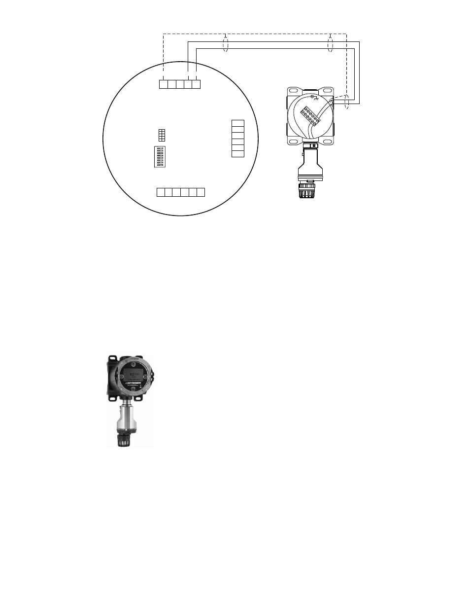
UD10-DCU Wired to GT3000 Detector with Sensor Termination Box
NOTE 1
GROUND THE SHIELD AT THE DISPLAY
UNIT END ONLY.
NOTE 2
HOUSINGS MUST BE ELECTRICALLY
CONNECTED TO EARTH GROUND.
SEE NOTE 1
A2512
RED
BLACK
GT3000
GAS DETECTOR
SENSOR TERMINATION BOX
RED
RED
BLA
CK
BLACK
GREEN
Sensor Connector
Power Supply Connector
LON Connect
or
J4
J3
J7
24 VDC
–
24 VDC
+
SHIELD
24 VDC
–
24 VDC
+
SHIELD
SHIELD
C
ALIBR
A
TE
24 VDC
–
4-20 mA
24 VDC
+
J4-1
J4-2
J4-3
J4-4
J4-5
J7
-6
J7
-5
J7
-4
J7
-3
J7
-2
J7
-1
SHIELD
2 B COM
2 A COM
SHIELD
1 B COM
1 A COM
J3-1
J3-2
J3-3
J3-4
J3-5
J3-6
UD10
DISPLAY UNIT
SW3
J2
ON
orientAtion
The device must be mounted in a vertical position only,
with the GT3000 pointing down.
liVe mAintenAnce
noTe
The sensor module on the GT3000 Gas Detector
can be hot swapped, i.e. replaced without
removing power or de-classifying the area. To
replace a GTX Transmitter connected to the
UD10-DCU with a new transmitter or a different
detector type, the area
must be de-classified.
noTe
Removing the sensor module with power applied
will result in a fault condition until a new sensor
module of the same type is installed. When
replacing an oxygen sensor, this action will also
result in an alarm condition as the decreasing
4-20 mA signal passes through the alarm range.
Inhibit response devices to prevent unwanted
actuation.
For complete information regarding sensor replacement
with the GT3000 Gas Detector, refer to the GT3000
instruction manual number 95-8616.