Connecting multiple ct recei, Connecting multiple ct receivers – B&K CT600.1 User Manual
Page 31
B K
&
S
B
IMPLY
ETTER!
25
Connecting Multiple CT Receivers
B K
&
S
B
IMPLY
ETTER!
Connecting Multiple CT Receivers
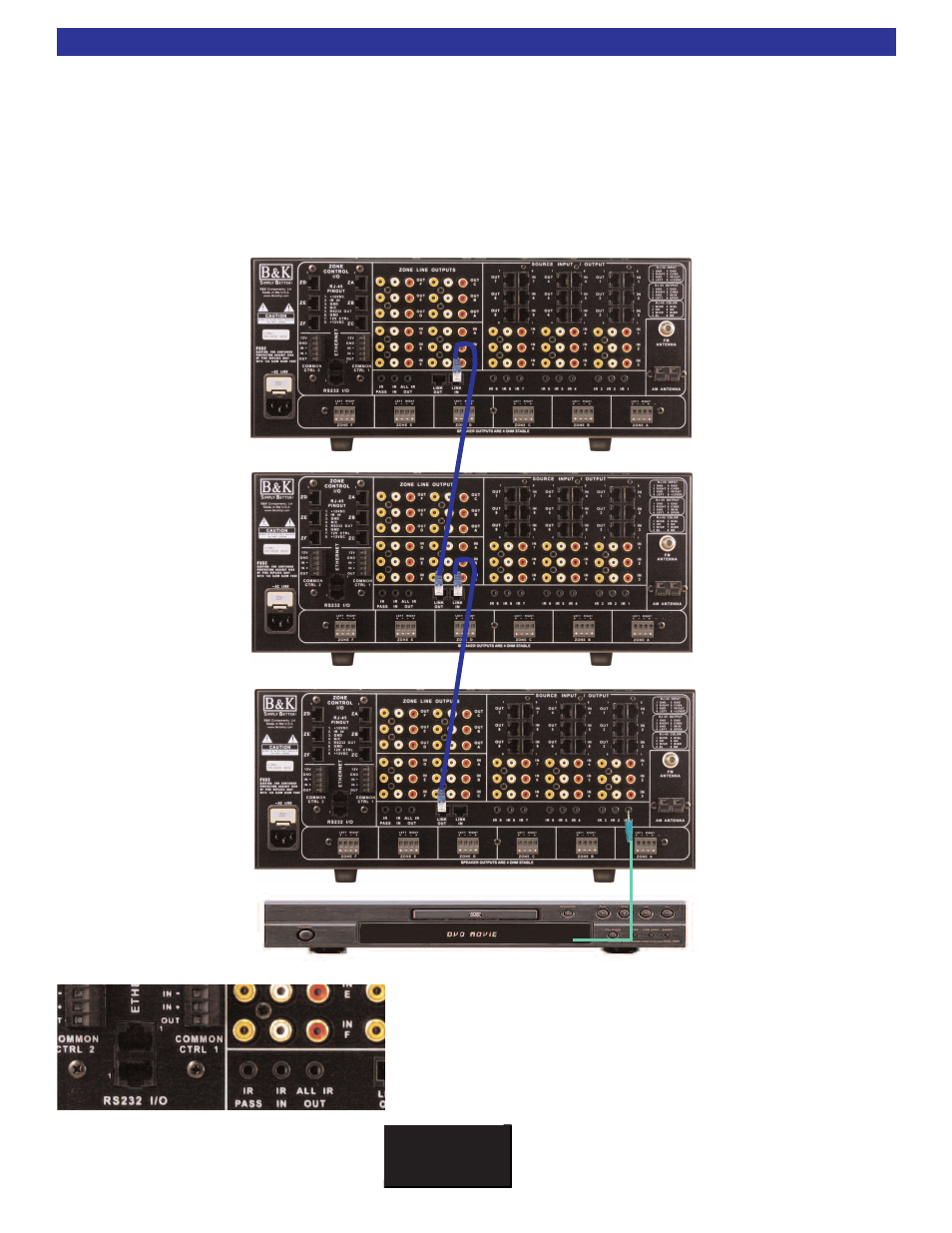
CT Receivers may be linked for up to 127 different zones. The Link Out RJ-45 of the first CT Receiver (CT#1
as shown) would connect with a straight CAT-5 cable to the Link In on the second CT Receiver (CT#2 as
shown). Then, the Link Out RJ-45 of the second CT Receiver (CT #2 as shown) would connect with a straight
CAT-5 cable to the Link In on the third CT Receiver. This would continue until all CT Receivers are linked
together. All flashers going to source pieces would be connected using the 1/8” mini jack Flasher Outs (IR
Outputs 1 through 9) on the FIRST CT Receiver, like shown.
Note: The LINK IN/LINK OUT is for IR only. Audio and video signals still need to be connected using the
buffered inputs and outputs. See Page 15 for more information.
CT #3
CT #2
CT #1
Along with the RJ-45 Link In and Out, there are also connec-
tions for IR through 1/8” minijack.
IR PASS - will pass anything that comes in from the IR IN.
IR IN- will control the CT Receiver and source pieces. See Page 49 for more
information.
ALL IR OUT- will send all IR information being sent to the unit either from
keypads or from the IR IN.