Ct receiver back panel – B&K CT600.1 User Manual
Page 11
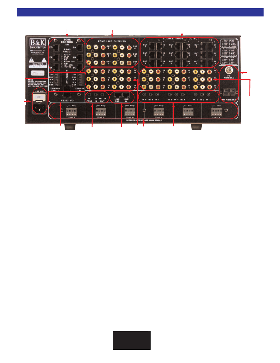
1.
6 Keypad control connections provide 12VDC power, common ground, RS-232 transmit, IR Data IN
and 12VDC control output triggers. The 300.3 has three keypad control connections. See page 19.
2.
6 Zone Audio/Video Line outputs for external amplification (factory fixed output or may be set to vari-
able output) and video monitors (1 per zone). On Screen Display (OSD) menu access is only provided
through the zone A video output. See pages 17 and 18.
3.
9 Buffered Audio/Video inputs and outputs for daisy-chain applications. See page 15.
4.
AM and FM Antenna connection. Internally split for multiple tuners in the CT600.3/300.3.
See page 23.
5.
9 Audio/Video shared Source inputs that may be shared throughout all zones. See page 14.
6.
9 Infrared emitter outputs for IR routing to source pieces. 1/8” (3.5mm) mini jack. See page 21.
7.
Removable four position phoenix speaker connections. Speaker connections are 4 ohm stable.
See page 16.
8.
6 Zone dedicated Audio/Video inputs for local sources, one per zone. See page 14.
9.
Link In and Link out for connecting multiple CT units. See page 25.
10.
IR pass, IR In and All IR Out 1/8” minijack connections for IR routing. See page 25
11.
RS-232 I/O and Ethernet RJ-45 for serial and network communication. See page 23
12.
AC Power inlet and AC fuse. See page 13.
13.
2 Common control connections with up to 24VAC or DC sensing on CT 600.1/600.3. One common
control on CT 300.3. See page 22.
CT Receiver Back Panel
B K
&
S
B
IMPLY
ETTER!
5
1
2
3
4
5
7
9
8
10
11
6
13
12