Ir emitter outputs, Local ir source control, Ir flasher emitter output – B&K CT600.1 User Manual
Page 27
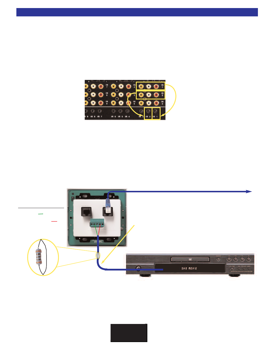
Note:
Additional resistance may be needed to be inserted
in line when running an IR flasher directly off a keypad.
Resistance will vary depending on length of run usually
between (100W
W - 500W
W). The resistor needs to be wired in
series with the flasher. The resistor may either be on the +
or - side of the connection. Additional resistance is needed
if the keypad is not able to control the shared sources con-
nected to the 9 IR outputs.
B K
&
S
B
IMPLY
ETTER!
21
Local IR Source Control
Local source control is accomplished by connecting IR emitters to the Alternate Master [IN] of the keypad.
Local control is not limited to one source, up to four IR emitters may be wired in series directly from the
keypad. NOTE: Additional resistance will need to be added when running emitters directly from the keypad.
Resistance may vary depending on the distance of the wire and the size of the wire. Typical in line resist-
ance will range from 100
W (for long runs) to 500W (for short runs). If resistance is not added, control of
shared sources may be lost. 12V Control voltages for local amplifiers or other voltage sensing devices may
also be terminated directly to the keypad’s Alternate Master [IN] using the 12V control and ground.
Multiple emitters should be connected in SERIES!
Most common brands of emitter may be used, how-
ever all Emitter output more consistent levels when
connected in series. Parallel connections may work
“some of the time”. Series connections are recom-
mended for consistent operation!
Standard 2 conductor 16 gauge
speaker wire is ideal for long runs
from the keypad to a Local TV or
device using an IR emitter. Utilizing
CAT-5 cable will also work well.
IR Emitter Outputs
Each of the nine shared sources may be controlled from any zone in the system using the CT Receiver built
in IR routing circuitry. By default, when the IR Flasher outputs are set to “selected input,” IR will route from
the keypad terminal to the IR output for only the input that is selected for that zone. This allows identical
source components to be used independently in the system. The flasher outputs may also be set to all input
configuration,where all 9 IR outputs will flash simultaneously. The IR outputs are compatible with any stan-
dard 1/8” (3.5mm) miniature flasher/emitter from Niles, Xantech, Elan, Sonance or Speakercraft, etc. The IR
outputs operate at 5V and may supply up to 10mA of current (475
W internal output resistance). All outputs
accommodate a wide range of carrier frequencies used in current source pieces. Make sure to use IR
shields when using multiple identical sources in the same rack.
By factory default, the IR outputs are set to ‘SELECTED INPUTS’ where IR routing is taking place.
IR Flasher Emitter Output
To CT Back Panel
Alternate Master Pin on CK 1.2
1. +12VDC IN
2. GROUND
3. RS-232 RECEIVE
4.KEYPAD DATA OUT
5. STATUS IN