Allied Telesis AT-S105 User Manual
Page 61
AT-S105 Management Software Web Browser User’s Guide
61
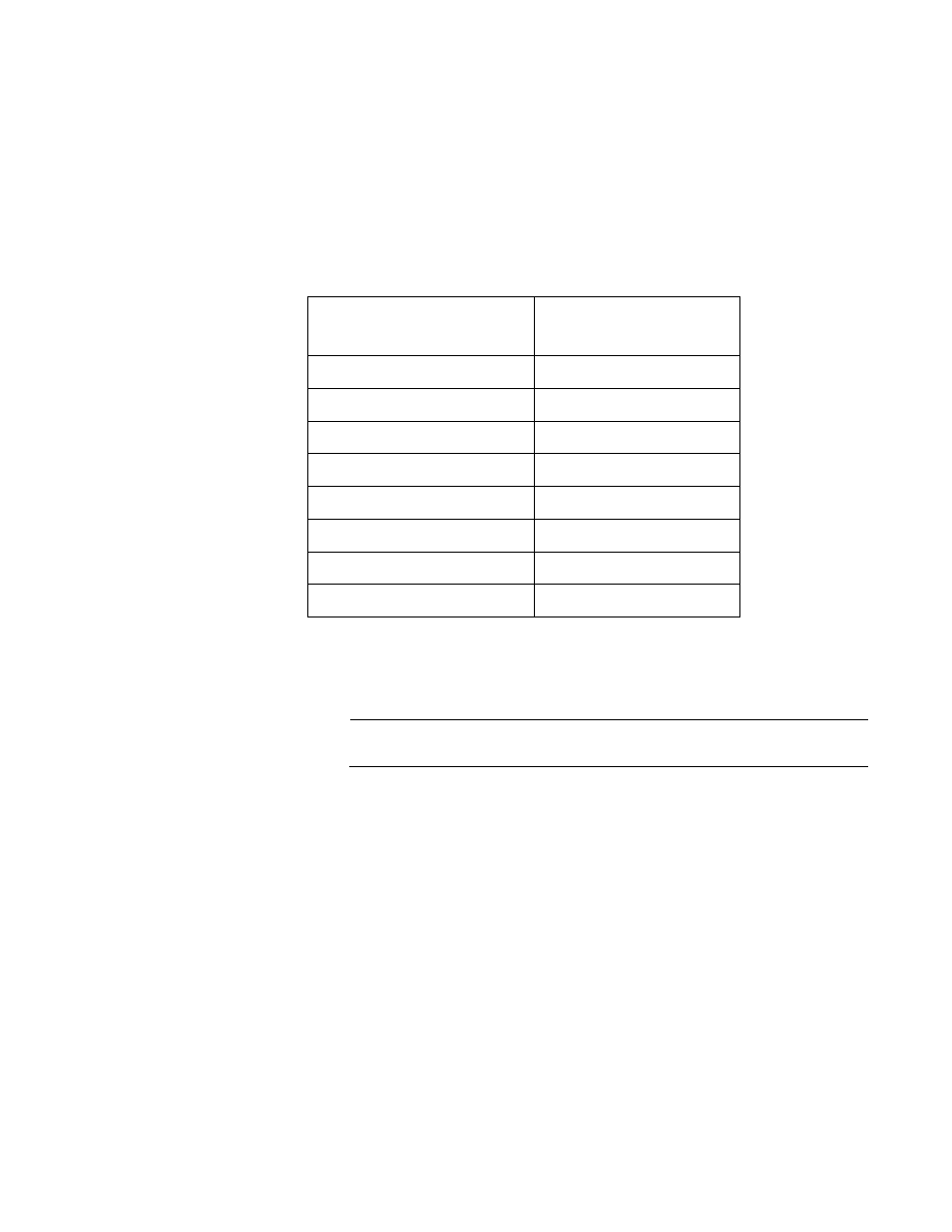
Each port on the AT-FS750/24POE and AT-FS750/48 switches has four
priority queues, 0 (low) to 3 (high). When a tagged packet enters a switch
port, the switch responds by placing the packet into one of the queues
according to the assignments shown in Table 1. A packet in a high priority
egress queue is typically transmitted from a port sooner than a packet in a
low priority queue.
For example, a tagged packet with a priority tag of 6 is placed in the
egress port’s highest priority queue of 3, while a packet with a priority tag
of 1 is placed in the lowest priority queue.
Note
QoS is disabled by default on the switch.
You can customize these priority-to-queue assignments using the
AT-S105 Management software. The procedure for changing the default
mappings is found in “Mapping CoS Priorities to Egress Queues” on
page 63. Note that because all ports must use the same priority-to-egress
queue mappings, these mappings are applied at the switch level. They
cannot be set on a per-port basis.
You can configure a port to ignore the priority levels in its tagged packets
and use a temporary priority level assigned to the port instead. For
instance, perhaps you decide that all tagged packets received by port 4
should be assigned a priority level of 5, regardless of the priority level in
the packets themselves. The procedure for overriding priority levels is
explained in “Configuring CoS” on page 65.
CoS relates primarily to tagged packets rather than untagged packets
Table 1. Default Mappings of IEEE 802.1p Priority Levels
to Egress Port Priority Queues
IEEE 802.1p Traffic Class
AT-FS750/xx Egress
Port Priority Queue
0
0
1
0
2
1
3
1
4
2
5
2
6
3
7
3