Specifications & dimensions – Red Lion MDC User Manual
Page 42
SPECIFICATIONS & DIMENSIONS
1. DISPLAY: 2x8, 0.3" (7 mm) high characters, negative image transmissive
LCD, with red LED backlighting.
2. POWER: Switch selectable for:
115 VAC ±10%, 50/60 Hz, 10 VA or
230 VAC ±10%, 50/60 Hz, 10 VA.
3. MEMORY: Non-volatile E
2
Prom retains all programming information
and values when power is removed or interrupted.
Power Cycles (ON/OFF): 100,000 minimum.
Data Retention: 10 years minimum.
4. SENSOR POWER: +12 VDC ± 25% @ 100 mA.
5. INPUTS (LEAD AND FEEDBACK): DIP Switch selectable to accept
input pulses from a variety of sources including outputs from CMOS or
TTL circuits and all standard RLC sensors.
Input Freq: 1 Hz to 20 KHz (Master Mode),
1 Hz to 12 KHz (Follower Mode).
LOGIC: Input trigger levels V
IL
= 1.5 V
MAX
; V
IH
= 3.75 V
MIN.
Current Sinking: Internal 7.8 KW pull up to +12 VDC, I
MAX
= 1.6 mA.
Current Sourcing: Internal 3.9 KW pull-down, 7.3 mA @ 28 VDC
MAX.
MAGNETIC PICKUP:
Sensitivity: 200 mV PEAK.
Hysteresis: 100 mV.
Input impedance: 3.9 KW @ 60 Hz.
Maximum input voltage: ±50V PEAK.
Note: For magnetic pickup input, the Sink/Source DIP switch must be
in the SRC position.
6. CONTROL LOOP RESPONSE:
10 msec (Master Mode), 20 msec (Follower Mode).
7. CONTROL ACCURACY:
0.01% of Speed Setpoint (Master Mode)
0.02% of Ratio Setpoint (Follower Mode)
Minimum Frequency Resolution: 0.00125 Hz
8. ERROR TRIM: ±4095 BITS.
9. ERROR GAIN: 0 to 99%.
10.RAMP RATE: (RAMP 1, RAMP 2, AND JOG RAMP)
1 Hz to 20 KHz/sec, set in user units/sec.
0.0001 to 1.9999 ratio units/sec (Ramp 1 & 2 in Follower Mode).
-40-
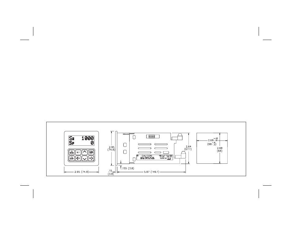
DIMENSIONS In inches (mm)
PANEL CUT-OUT
Note: Recommended minimum clearance (behind the panel) for mounting clip installation is 3.0" (76.2) H x 4.0" (101.6) W.