Red Lion MDC User Manual
Page 35
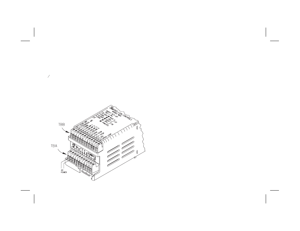
WIRING CONNECTIONS
When wiring the unit, remove the terminal block and use the numbers on
the top label to identify the position number with the proper function. All
conductors should meet voltage and current ratings for each terminal. Also
cabling should conform to appropriate standards of good installation, local
codes and regulations. It is recommended that power supplied to the unit be
protected by a fuse or circuit breaker. Strip the wire, leaving approximately
1
4
" bare wire exposed (stranded wires should be tinned with solder). Insert the
wire into the terminal and tighten down the screw until the wire is clamped in
tightly. Each terminal can accept up to two 18-gage wires. After the terminal
block is wired, install it in the proper location at the rear of the unit. Wire each
terminal block in this manner.
AC POWER WIRING
The AC power is connected to the bottom terminals, TBA 1 & 2, marked AC
PWR. The voltage selector switch, located at the side of the unit, is used to select
the proper voltage. The switch is a slide movement type and can be set using a
small screwdriver. If the switch is towards the front of the unit, it is set for 115
VAC input. If the switch is towards the rear of the unit, it is set for 230 VAC
input. The switch is in the 230 VAC position when shipped from the factory.
Note: Before applying power to the unit make sure the AC power switch is set for
the proper voltage setting.
To reduce the chance of noise spikes entering the AC line and affecting the
unit, the AC power should be relatively “clean” and within the specified
±10% variation limit. Connecting power from heavily loaded circuits or
circuits that also power loads that cycle on and off, (contactors, relays,
motors, etc.) should be avoided.
DC OUTPUT POWER WIRING
The DC Output power connections are bottom terminals TBA 3 & 4
marked +12 VDC and common. This source is capable of supplying 12 VDC
±25% at 100 mA to power input sensors or other external devices. These
terminals CANNOT be used to supply DC power to the MDC.
-33-
TERMINAL CONNECTIONS