Red Lion MDC User Manual
Page 38
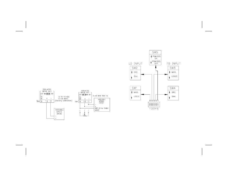
ISOLATED DRIVE OUTPUT
Before connecting the MDC to the motor drive, refer to the Isolated Drive
Output Calibration section to determine if the MDC’s analog drive output needs
calibration. Most applications require calibration of the motor drive only.
The MDC can be operated with an internal or external voltage reference. The
jumper above the bottom rear terminal block selects the internal reference
when in the position closest to the board edge. The unit is shipped in this
configuration. The internal reference is factory calibrated to provide 10.0 VDC
full scale output. If your drive requires an input signal other than 0 to 10 VDC,
refer to the section, Calibrating the Isolated Drive Output. If your drive does
not have a process control input, the MDC may be wired to the drive in place of
the drive’s external speed potentiometer. In this case, set the jumper in the
EXTERNAL position. The full scale output voltage is the “high” side of the
drive’s external potentiometer connection.
Wiring the MDC to the motor drive:
DIP SWITCH SET-UP
The DIP switches are accessible through the side of the MDC. The DIP
switch positions and their functions are shown below:
-36-
INTERNAL REFERENCE
EXTERNAL REFERENCE
MDC wired to process control input on the
variable speed drive. Reference voltage
supplied by the MDC.
MDC wired in place of an external speed pot.
The “Top of Pot” reference voltage is supplied
from the variable speed drive. (External
speed pot must be removed.) A register of
equal value to the external pot may be
needed across pins 9 and 11 of the MDC to
stabilize the voltage level from the drive.