4 puf instrument, 1 connectors, 1 connectors 4 – Dwyer Series PUF User Manual
Page 8: General description
1: General Description
4
1.4
PUF Instrument
The PUF is a microprocessor controlled instrument operated through a menu system using an inbuilt LCD display
and keypad. It can be used to display the instantaneous fluid flow rate or velocity, together with totalized values,
or act as a data logger. When operating in the data logger mode, the logged data can be output directly to a PC or
printer using the RS232/USB interface or stored in the instrument’s non-volatile memory for downloading at a
later time. Up to 98k logging events can be stored internally.
The instrument can also provide a variable current or ‘pulse’ (volumetric or frequency) output that is proportional
to the detected flow rate. These outputs, which can be used with a range of external interface devices such as
those found in building management or site monitoring systems, can be calibrated to suit a particular flow range.
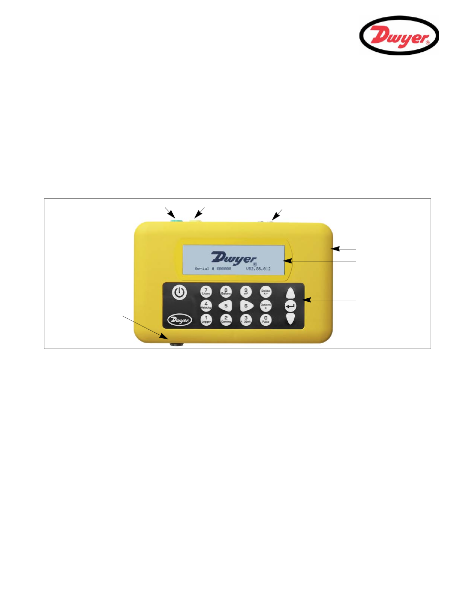
1.4.1 Connectors
Figure 1.3 Instrument details
Transducer connections
The transducers are connected to two color-coded miniature coaxial sockets located on the top of the instrument.
Using the red/blue connector cables provided, the upstream transducer should always be connected to the RED
socket and the downstream transducer to the BLUE one for a positive flow reading. It is safe to connect or
disconnect the cable while the instrument is switched on.
RS232 and USB connections
RS232 and USB cables are included as part of the PUF kit. These can be connected to the yellow 8-pin
connector on the top of the flowmeter as shown in Figure 1.3. The RS232 cable is terminated with a 9-pin ‘D-type’
connector.
4 to 20 mA and Pulse output connection
The 4 to 20 mA / ‘pulse’ output cable should be connected to the green 7-pin connector on the top of the
flowmeter, as shown in Figure 1.3. A single cable that can be adapted for use for either of these output functions
is included in the PUF kit. The ‘tails’ on the free end of the cable must be terminated to suit the intended
application.
Red – 4 to 20 mA positive
Black – 4 to 20 mA negative
White – Pulse output
Green – Pulse return
Thick Black – Cable screen
Keypad
LCD Display
Battery Charger
4 to 20 mA / Pulse Output
RS232 / USB Output
Transducer Cables
Reset pin-hole