4 test block, Troubleshooting – Dwyer Series PUF User Manual
Page 52
5: Troubleshooting
48
5.4
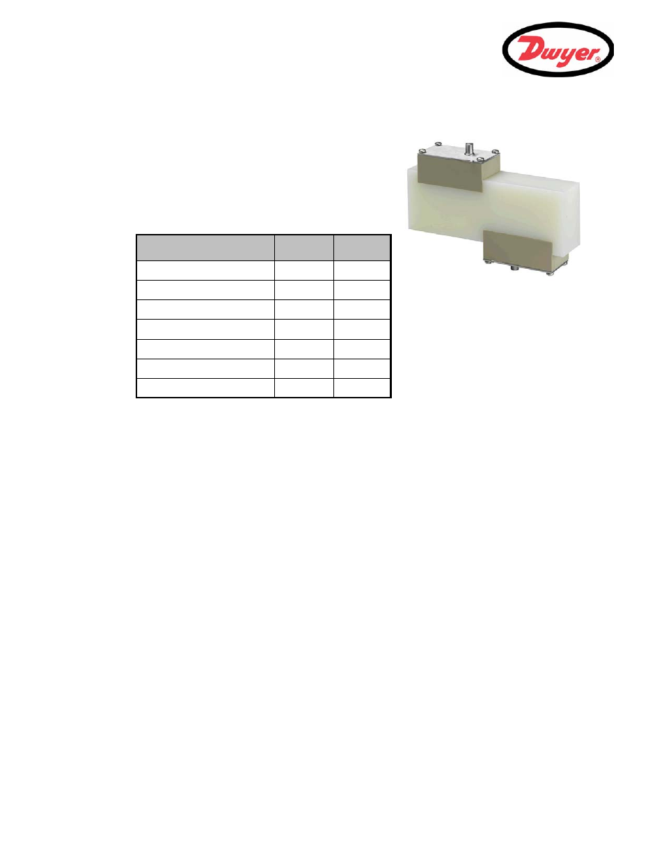
Test Block
A test block is included with the PUF equipment to allow the
transducers and inter-connecting cables to be functionally
checked.
1.
Switch
ON the instrument.
2.
Select
Quick start and enter the parameters shown in
the table below for the appropriate transducer type (A or B):
3.
When the above data is entered, the
SENSOR SEPARATION screen will be displayed.
4.
Use the
UP/DOWN scroll key to go to the SENSOR SELECTION menu. Select the appropriate sensor (the
default will be "
A") and press the ENTER key to return to the SENSOR SEPARATION menu.
5.
Select
Sensor mode and position the cursor at Diagonal and press ENTER to return to the SENSOR
SELECTION menu.
6.
Select
Exit and press the ENTER key to return to the SENSOR SEPARATION screen.
7.
Check that the parameters displayed are correct.
8.
Apply acoustic couplant to the sensors and attach them to the test block with the connectors positioned
towards the center of the test block as shown, and temporarily secure them in place using elastic bands or
tape.
9.
Connect the sensors to the PUF instrument using the cables provided.
10. Press
ENTER to go to the FLOW READING screen.
11. Select the
Options key to go to the FLOW READING OPTION menu and set the Damping to at least 10
seconds.
12. Select
Exit and press the ENTER key to return to the FLOW READING menu.
13. The flow reading value displayed is not important. The fact that a reading is obtained indicates that the
instrument is functioning. This value may fluctuate but this is normal.
14. The signal strength indicator at the left of the display should show 3–4 bars.
Parameter
A Sensor
B Sensors
Pipe outside diameter
1.18 inch
1.97 inch
Pipe wall thickness
0.55 inch
0.87 inch
Pipe lining thickness
0.0
0.0
Pipe wall material
Plastic
Plastic
Fluid type
Water
Water
Mode
Diagonal
Diagonal
Temp
68°F
68°F
Figure 5.2 Test block